




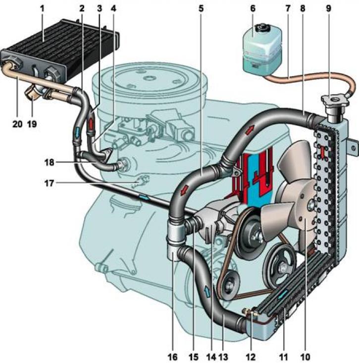
Carburetor engine cooling system parts: 1 - heater radiator; 2 - coolant drain hose from the heater radiator; 3 - coolant supply hose to the heater tap; 4 - coolant drain pipe from the cylinder head; 5 - bypass hose; 6 - expansion tank; 7 - expansion tank connecting hose; 8 - coolant supply hose to the radiator; 9 - radiator cap; 10 - radiator electric fan; 11 - cooling system radiator; 12 - Electric fan switch sensor; 13 - coolant drain hose from radiator; 14 - Coolant pump; 15 - coolant supply hose to the pump; 16 - thermostat; 17 - coolant temperature gauge sensor; 18 - coolant outlet hose from the intake manifold; 19 - heater tap; 20 - coolant drain pipe from the heater radiator
The cooling system maintains the optimal thermal conditions of the engine by means of controlled heat removal from the hottest parts. The engine cooling system is liquid, hermetically sealed, with forced circulation of the coolant and an expansion tank.
Connected to the cooling system interior heater radiator car. Heated coolant from the cylinder head flows through a hose through an open tap into the heater radiator, and then (through the liquid drain tube) - in the coolant pump.
Coolant pump - centrifugal, driven by a V-belt drive from the crankshaft pulley. The pump consists of a housing and a cover made of aluminum alloy. The cover is fastened with nuts to four studs screwed into the pump housing. A sealing gasket is installed between the housing and the cover. The pump shaft rotates in a double-row sealed bearing. The flange of the pump drive pulley is pressed onto the front end of the shaft, and a cast iron or plastic impeller is pressed onto the rear end.
Radiator - vertical, tubular-plate, with two plastic tanks and an aluminum core. The radiator is mounted on two rubber cushions and is attached to the body with two bolts. The radiator filler neck is sealed with a plug and connected with a hose to expansion tank. The radiator cap has an outlet (steam) valve, pressed by a spring to the seat belt of the filler neck, and an inlet valve, through which the radiator is connected to the expansion tank. The inlet valve is not pressed against the seat and has a gap of 0.5-1.1 mm, which ensures the inlet and outlet of coolant into the expansion tank during heating or cooling. With a sharp increase in temperature or boiling of the liquid, the inlet valve does not have time to release the liquid into the expansion tank and closes, disconnecting the system from the expansion tank. When, due to further heating of the liquid, the pressure increases to 50 kPa, the outlet valve opens and some of the liquid begins to flow into the expansion tank. The expansion tank is closed with a plug with a rubber valve, maintaining the pressure in the tank close to atmospheric.
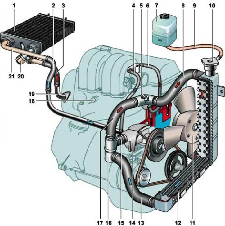
Details of the injection engine cooling system: 1 - heater radiator; 2 - coolant drain hose from the heater radiator; 3 - coolant supply hose to the heater tap; 4 - coolant drain hose from the throttle body heating unit; 5 - sensor (control systems) coolant temperature; 6 - coolant supply hose to the throttle body heating unit; 7 - expansion tank; 8 - coolant supply hose to the radiator; 9 - expansion tank connecting hose; 10 - radiator cap; 11 - cooling system radiator; 12 - radiator electric fan; 13 - coolant drain hose from radiator; 14 - Coolant pump; 15 - coolant supply hose to the pump; 16 - thermostat; 17 - bypass hose; 18 - coolant temperature gauge sensor; 19 - coolant drain pipe from cylinder head; 20 - heater tap; 21 - coolant drain pipe from the heater radiator
Electric fan installed behind the radiator. To reduce noise during operation, the fan impeller blades have a variable angle and pitch along the radius. The electric fan of a carburetor engine is switched on by a sensor screwed into the lower part of the right radiator tank. On early-production cars with constant forced ventilation, the fan switch sensor and electric fan were not installed. The fan impeller was attached to the coolant pump pulley and rotated constantly when the engine was running. On an injection engine, the electric fan is controlled by ECU commands (via relay). The initial data for these commands is the signal from the coolant temperature sensor installed in the outlet pipe of the cooling system.
Thermostat cooling system serves to maintain the required thermal mode of engine operation and accelerate its warming up. When the coolant temperature is below 80°C, the main thermostat valve is closed and the bypass valve is open. The liquid circulates from the cooling jacket of the cylinder block through the thermostat bypass valve to the pump, which again supplies the liquid to the cooling jacket, bypassing the radiator (small circle). This ensures rapid engine warm-up. The temperature at which the main thermostat valve begins to open should be in the range of 80.6-81.5°C. The full stroke of the main valve should be at least 6 mm. When the liquid heats up above 94°C, the main thermostat valve opens completely and the bypass valve closes. Liquid flows from the cooling jacket through the supply hose to the radiator. From the radiator, the liquid passes through the main thermostat valve through the outlet hose to the pump, which again supplies liquid to the cooling jacket (big circle). In the temperature range of 80-94°C, the thermostat valves are in an intermediate position and the liquid circulates both in the small and large circles. Regardless of the position of the thermostat valves, when the heater tap is open, the liquid always circulates through the heater radiator. In addition, the liquid constantly circulates through the heating unit of the intake manifold or the throttle body (on an injection engine).