
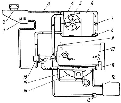
Pic. 7. Schematic diagram of the cooling system: 1 - expansion tank; 2 - plug of the expansion tank; 3 - hose from the expansion tank to the radiator; 4 - fan casing; 5 - electric fan; 6 - radiator; 7 - sensor for turning on the electric fan; 8 - radiator drain plug; 9 - drain plug of the cylinder block; 10 - engine; 11 - coolant pump; 12 - radiator of the body cabin heater; 13 - the edge of the heater; 14 - inlet pipeline; 15 hose for draining fluid from the intake manifold and carburetor; 16 - thermostat. Dashed arrows show fluid circulation with a cold engine (small circle), and solid arrows - when heated (big circle)
Hot liquid is diverted from the cylinder head to the radiator or, bypassing it (depending on the position of the thermostat valves) enters the pump, from which it is directed to the engine block.
The engine cooling system includes a heater 12 of the body interior, the liquid into which comes from the cylinder head through the outlet pipe and the valve 13 of the heater and is discharged to the pump, as well as the heating of the carburetor, the liquid into which comes from the jacket of the inlet pipeline 14 and is discharged to the pump through the hose 15.
To compensate for changes in the volume and pressure of the coolant, there is an expansion tank 1, which is connected by hoses to a thermostat in the fluid inlet area from the radiator and to the radiator
Coolant pump
Centrifugal type, driven by a toothed belt engine; mounted on cylinder block 3 (pic. 8). The roller 5 is placed in the housing 2 on a double-row ball bearing 8, which is locked with a screw 1. A toothed pulley 9 and an impeller 4 are pressed onto the roller, which is sealed with an oil seal 7 and an o-ring 6 made of graphite composition.
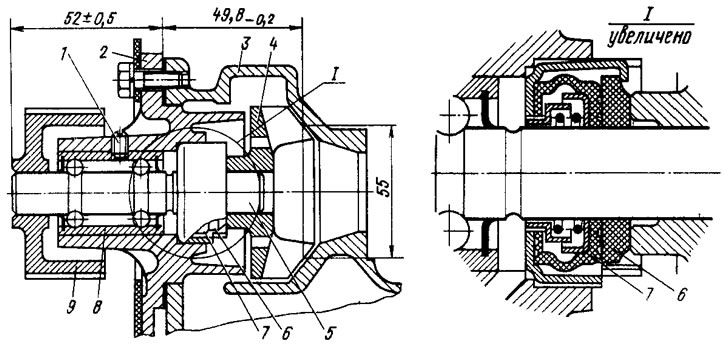
Pic. 8. Coolant pump
Electric fan
Interchangeable with the electric fan of the VAZ-2103 engine. The fan is turned on and off depending on the coolant temperature by a sensor screwed into the right radiator tank.
Radiator
Prefabricated, aluminum, with plastic tanks; radiator core - with two rows of horizontal tubes. The radiator is mounted on rubber pads. The left radiator tank is connected by a hose to the expansion tank. The expansion tank is closed with a stopper with valves. The pressure of the beginning of the opening of the exhaust valve is not less than 1.2 kgf / cm2, inlet - 0.034-0.13 kgf / cm2.
Thermostat
Non-separable, with a solid temperature-sensitive element, with the main 9 (pic. 9) and 6 bypass valves operating in the coolant temperature range of 87-102°C.
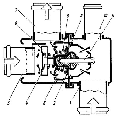
Pic. 9. Thermostat: 1 - inlet pipe (from the radiator); 2 - rubber insert; 3 - solid thermosensitive filler; 4 - additional valve spring; 5 - inlet pipe (from the engine); 6 - bypass valve; 7 - outlet pipe (to the pump); 8 - main valve spring; 9 - main valve; 10 - branch pipe (from expansion tank); 11 - piston