




Open large image in new tab »
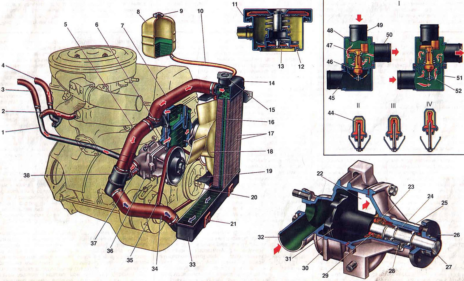
Fig. 6. Engine cooling system.
1. The pipe that drains liquid from the heater radiator to the coolant pump: 2. The hose that drains the coolant from the inlet pipe; 3. Hose for draining coolant from the heater radiator; 4. Hose for supplying liquid to the heater radiator; 5. Thermostat bypass hose; 6. Cooling jacket outlet pipe; 7. Radiator supply hose; 8. Expansion tank; 9. Tank cap; 10. Hose from the radiator to the expansion tank; 11. Radiator cap; 12. Outlet (steam) plug valve; 13. Inlet valve; 14. Upper radiator tank; 15. Radiator filler neck; 16. Radiator pipe; 17. Radiator cooling fins; 18. Fan shroud; 19. Electric fan; 20. Coolant pump drive pulley; 21. Rubber support; 22. Window on the cylinder block side for supplying coolant; 23. Oil seal cage; 24. Coolant pump shaft bearing; 25. Pump cover; 26. Pump drive pulley hub; 27. Pump shaft; 28. Locking screw; 29. Seal cuff; 30. Pump body; 31. Pump impeller; 32. Pump inlet; 33. Lower radiator tank; 34. Radiator drain hose; 35. Coolant pump drive belt; 36. Coolant pump; 37. Coolant supply hose to the pump; 38. Thermostat; 39. Rubber insert; 40. Inlet pipe (from the radiator); 41. Main valve; 42. Bypass valve; 43. Thermostat housing; 44. Bypass hose branch pipe; 45. Coolant supply hose branch to the pump; 46. Thermostat cover; 47. Working element piston; I. Thermostat operation diagram; II. Liquid temperature less than 80°C; III. Liquid temperature 80 - 94°C; IV. Liquid temperature is more than 94°C.
1. The pipe that drains liquid from the heater radiator to the coolant pump: 2. The hose that drains the coolant from the inlet pipe; 3. Hose for draining coolant from the heater radiator; 4. Hose for supplying liquid to the heater radiator; 5. Thermostat bypass hose; 6. Cooling jacket outlet pipe; 7. Radiator supply hose; 8. Expansion tank; 9. Tank cap; 10. Hose from the radiator to the expansion tank; 11. Radiator cap; 12. Outlet (steam) plug valve; 13. Inlet valve; 14. Upper radiator tank; 15. Radiator filler neck; 16. Radiator pipe; 17. Radiator cooling fins; 18. Fan shroud; 19. Electric fan; 20. Coolant pump drive pulley; 21. Rubber support; 22. Window on the cylinder block side for supplying coolant; 23. Oil seal cage; 24. Coolant pump shaft bearing; 25. Pump cover; 26. Pump drive pulley hub; 27. Pump shaft; 28. Locking screw; 29. Seal cuff; 30. Pump body; 31. Pump impeller; 32. Pump inlet; 33. Lower radiator tank; 34. Radiator drain hose; 35. Coolant pump drive belt; 36. Coolant pump; 37. Coolant supply hose to the pump; 38. Thermostat; 39. Rubber insert; 40. Inlet pipe (from the radiator); 41. Main valve; 42. Bypass valve; 43. Thermostat housing; 44. Bypass hose branch pipe; 45. Coolant supply hose branch to the pump; 46. Thermostat cover; 47. Working element piston; I. Thermostat operation diagram; II. Liquid temperature less than 80°C; III. Liquid temperature 80 - 94°C; IV. Liquid temperature is more than 94°C.
The engine cooling system is liquid, closed type, with forced circulation of liquid. The capacity of the system is 9.85 liters, including the heating system of the body interior. The cooling system consists of the following elements: coolant pump 36, radiator, expansion tank 8, pipelines and hoses, electric fan 19, cooling jackets of the block and cylinder head.
When the engine is running, the liquid heated in the cooling jackets flows through the outlet pipe 6 along the hoses 5 and 7 into the radiator or thermostat, depending on the position of the thermostat valves. The coolant is then sucked in by the pump 36 and fed back into the cooling jackets.
The engine cooling system is liquid, closed type, with forced circulation of liquid. The capacity of the system is 9.85 liters, including the heating system of the body interior. The cooling system consists of the following elements: coolant pump 36, radiator, expansion tank 8, pipelines and hoses, fan 19, cooling jackets of the block and cylinder head.
When the engine is running, the liquid heated in the cooling jackets flows through the outlet pipe 6 along the hoses 5 and 7 into the radiator or thermostat, depending on the position of the thermostat valves. The coolant is then sucked in by the pump 36 and fed back into the cooling jackets.
The coolant level is checked on a cold engine (at a temperature of plus 15-20°C) by the liquid level in the expansion tank 8, which should be 3-4 mm above the "MIN" mark.
To control the coolant temperature, there is a sensor installed in the cylinder head and an indicator on the instrument panel. During normal engine operating temperature conditions, the indicator arrow is at the beginning of the red field of the scale within 80-100°C. When the arrow moves into the red zone, it indicates an increased engine thermal mode, which may be caused by problems in the cooling system (loose pump drive belt, insufficient coolant, faulty thermostat or electric fan), as well as difficult road conditions.
The fluid is drained from the system through drain holes closed with plugs: one in the left corner of the lower tank 33 of the radiator, the other in the cylinder block on the left in the direction of vehicle movement.
The car's interior heater is connected to the cooling system. Heated liquid from the cylinder head flows through hose 4 through the tap into the heater radiator, and is sucked out by pump 36 through hose 3 and tube 1.
Coolant pump
The coolant pump is a centrifugal type, driven from the crankshaft pulley by the generator drive V-belt. The pump is attached to the cylinder block on the right side through a sealing gasket.
The housing 30 and the cover 25 of the pump are cast from an aluminum alloy. A shaft 27 is installed in the cover of the bearing 24, which is locked with a screw 28. The bearing 24 is double-row, non-separable, without an inner race. The bearing is filled with grease during assembly and is not lubricated further. The impeller 31 is pressed onto the shaft 27 on one side, and the hub 26 of the pump drive pulley is pressed on the other. The end face of the impeller in contact with the sealing ring is hardened by high-frequency currents to a depth of 3 mm. The sealing ring is pressed against the impeller by a spring through a rubber cuff 29. The gland is non-separable, consists of an outer brass race 23, a rubber cuff and a spring. It is pressed into the cover 25 of the pump.
The pump body has a receiving branch pipe 32 and a window 22 towards the cylinder block for supplying coolant by the pump. With normal tension of the pump drive belt, its deflection under a force of 10 kgf should be within 10-15 mm.
Electric fan
The fan has four blades and is made of plastic. The fan blades have a variable angle of installation along the radius and a variable pitch along the hub to reduce noise. The fan is installed on the electric motor shaft and pressed with a nut. For better efficiency, the fan is in a casing 18, which is bolted to the radiator brackets. The electric motor assembled with the fan is installed on three rubber bushings and fastened with nuts to the studs of the casing 18 of the fan.
The original is available on the website VAZBOOK.RU
Electric fan 19 is switched on and off automatically depending on the liquid temperature using a TM-108 sensor installed in the lower radiator tank on the left side. The sensor contact closing temperature should be within 89-95°C, and opening temperature within 84-90°C.
In variant versions, VAZ-21061 vehicles can be equipped with fans with a mechanical drive from the hub of the coolant pump shaft.
Radiator
The radiator with upper and lower tanks, with two rows of brass vertical tubes and tinned cooling plates is attached with four bolts to the front of the body and rests on rubber supports 21.
Filler neck 15 of the radiator is closed by plug 11 and connected by hose 10 to translucent plastic expansion tank 8. The radiator plug has inlet valve 13 and outlet valve 12, through which the radiator is connected by hose to the expansion tank. The inlet valve is not pressed against the gasket (gap 0.5-1.1 mm) and allows the coolant to flow into and out of the expansion tank when the engine is heating and cooling.
Since 1988, cars have been equipped with radiators with an aluminum core and plastic tanks.
Thermostat and operation of the cooling system
The cooling system thermostat accelerates engine warm-up and maintains the required thermal mode of engine operation. At the optimal thermal mode, the coolant temperature should be 85-95°C.
Thermostat 38 consists of body 43 and cover 46, which are rolled together with seat of main valve 41. Thermostat has inlet branch pipe 40 for intake of cooled liquid from radiator, branch pipe 44 of bypass hose 5 for bypass of liquid from cylinder head to thermostat and branch pipe 45 for supply of coolant to pump 36.
The main valve is installed in the thermoelement cup, in which the rubber insert 39 is rolled. In the rubber insert there is a polished steel piston 47, fixed on a fixed holder. Between the walls and the rubber insert there is a heat-sensitive solid filler. The main valve 41 is pressed by a spring to the seat. Two posts are fixed on the valve, on which the bypass valve 42 is installed, pressed by a spring.