




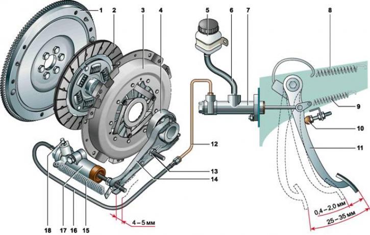
Clutch details: 1 - flywheel; 2 - driven clutch disc; 3 - basket; 4 - release bearing with clutch; 5 - hydraulic reservoir; 6 - hose; 7 - master cylinder of the clutch release hydraulic drive; 8 - clutch pedal servo spring; 9 - clutch pedal return spring; 10 - clutch pedal travel limiting screw; 11 - clutch pedal; 12 - Clutch release hydraulic drive pipeline; 13 - fork ball joint; 14 - clutch release fork; 15 - clutch release fork release spring; 16 - hose; 17 - clutch release hydraulic drive slave cylinder; 18 - bleed nipple
The vehicle clutch is dry, single-disk, permanently closed, and is designed to connect the engine crankshaft and the primary shaft of the gearbox with the ability to briefly stop the transmission of torque. The design ensures smooth engagement of the clutch due to the mutual short-term slippage of its working disks.
The clutch is mounted on the flywheel and is covered by an aluminum housing, which is attached to the cylinder block with four bolts. On the other side, the housing is connected to the gearbox housing.
The hub is freely mounted on the splines of the primary shaft of the gearbox, on which is installed slave disk, divided by radial slots into twelve sectors. Friction linings made of a special material are riveted to the driven disk on both sides. Torque from the driven disk to its hub is transmitted through a spring-friction damper (torsional vibration damper).
Basket (clutch master part) is attached to the flywheel with six bolts and includes a pressure plate, a casing and a diaphragm pressure spring. The pressure plate is movably attached to the casing. Under the action of the diaphragm spring, the driven disk is clamped between the pressure plate and the flywheel.
The clutch is disengaged hydraulic drive with hanging pedal. Pedal the clutch pedal is mounted on a common axis with the brake pedal, secured to the bracket of the engine compartment partition. A spring is attached to the upper part of the pedal, reducing the force of disengaging the clutch. A pusher is pivotally attached to the pedal. The hemispherical end of the pusher enters the piston seat of the master cylinder of the clutch release drive. The pedal travel is limited on one side by an adjusting screw, and on the other by the piston travel in the cylinder.
Master cylinder is located in the engine compartment and is attached with two nuts to the studs of the pedal assembly. The cylinder is connected with a hose to the reservoir of the clutch release hydraulic drive. Tank is installed on the left side of the engine compartment partition. The tank is made of translucent plastic, which makes it easier to check the fluid level in the drive. A corrugated rubber fluid damper is installed in the tank lid. A hole is made in the lid to connect the tank cavity with the atmosphere.
The main cylinder is connected to a pipe fitting that supplies fluid from the main cylinder to the working cylinder, the other end of this pipe is connected to the tip of the hydraulic drive hose. The hose tip is secured to the body bracket with a clamp. The other end of the hose is connected to the working cylinder of the clutch release hydraulic drive.
Slave cylinder is attached to the clutch housing with two bolts. The cylinder rod is a pusher clutch release forks, mounted on a ball joint in the clutch housing. One end of the fork rests on the adjusting nut of the pusher, and the other is pressed against the release bearing clutch. The bearing sleeve is placed on the guide sleeve of the front cover of the gearbox and has the ability to move longitudinally.
When the engine is running, the leading and driven parts of the clutch rotate as a single unit, transmitting torque from the engine crankshaft to the primary shaft of the gearbox. When the clutch pedal is pressed, the force is transmitted through the hydraulic drive from the slave cylinder to the clutch release fork, which, turning on the ball joint, moves the release bearing along the guide sleeve. The bearing acts on the diaphragm spring of the basket, it bends on the support rings and moves the pressure plate away from the driven disk. In this case, the primary shaft of the gearbox is disconnected from the engine crankshaft, the transmission of torque stops. When the pedal is released, all clutch parts return to their original position under the action of the springs.