The leading part of the clutch is a non-separable assembly placed in the crankcase 7 and including a casing 1 (pic. 60), pressure plate 4, pressure spring 2 and a number of other details. This assembly is attached to the flywheel with 6 bolts 8. Between the flywheel and the pressure plate on the splines of the drive shaft 9 of the gearbox is a driven disc 5 with friction linings, which is connected to the hub through a torsional vibration damper.
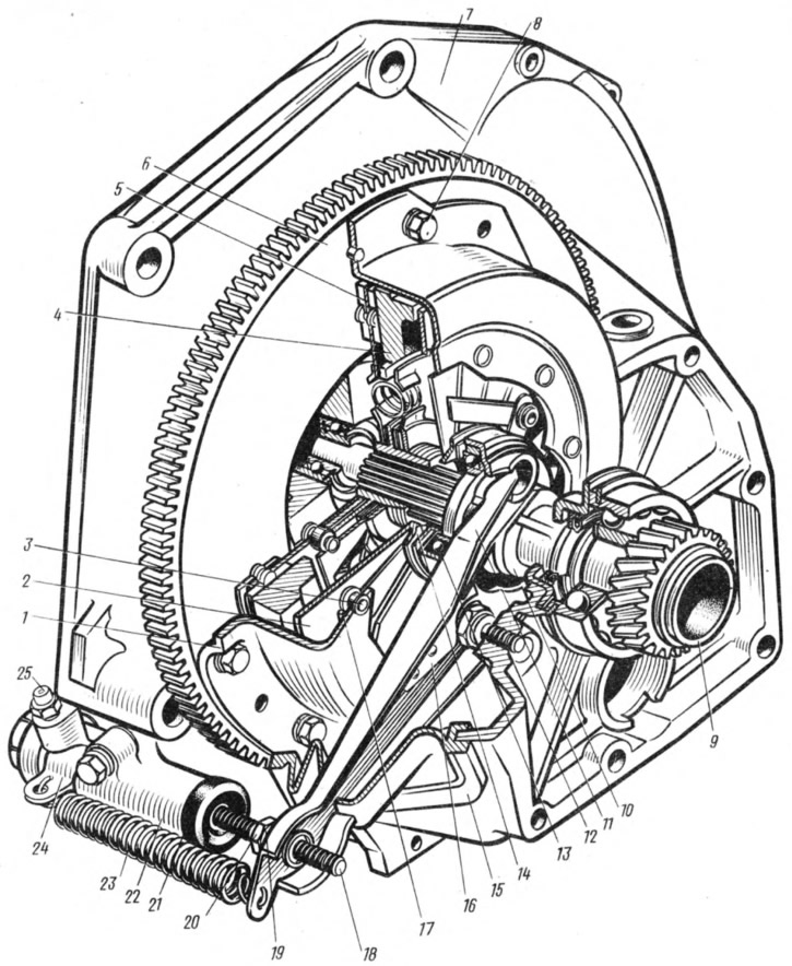
Pic. 60. Clutch:
1 - clutch cover; 2 - pressure spring; 3 - step rivet; 4 - pressure plate; 5 - driven disk; 6 - flywheel; 7 - clutch housing; 8 - bolt; 9 - transmission drive shaft; 10 - clutch release bearing; 11 - clutch release fork; 12 - fork ball joint; 13 - clutch release bearing; 14 - thrust flange of the pressure spring; 15 - clutch release fork cover; 16 - spring; 17 - support ring of the pressure spring; 18 - pusher of the clutch release fork; 19 - adjusting nut; 20 - locknut; 21 - protective cap; 22 - clutch release cylinder (worker); 23 - retraction spring of the fork; 24 - spring bracket; 25 - fitting for pumping.
The clutch release bearing 13 acts on the pressure spring petals through the thrust flange 14, which is connected to the clutch housing through the connecting plates and rivets 3.
Clutch drive - hydraulic. The clutch master cylinder is fixed on the bracket 11 (pic. 61) clutch and brake pedals, and the working cylinder 22 (see fig. 60) - on the clutch housing.
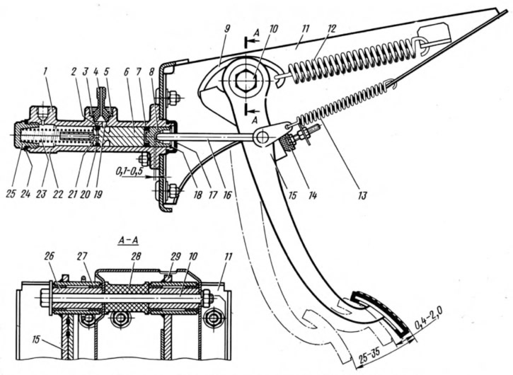
Pic. 61. Pedal and clutch master cylinder:
1 - main cylinder body; 2 - compensation hole; 3 - fitting gasket; 4 - fitting; 5 - lock spring washer; 6 - piston of the main cylinder; 7 - sealant; 8 - pusher piston; 9 - hook; 10 - axis of the clutch and brake pedals; 11 - bracket for clutch and brake pedals; 12 - clutch pedal reinforcing spring (servo spring); 13 - release spring of the clutch pedal; 14 - clutch pedal stroke limiter; 15 - clutch pedal; 16 - pusher; 17 - protective cap; 18 - retaining ring; 19 - bypass hole; 20 - sealing ring (ring valve); 21 - piston bypass hole; 22 - working cavity of the cylinder; 23 - spring; 24 - gasket; 25 - cork; 26 - inner sleeve of the pedal; 27 - outer pedal sleeve; 28 - spacer sleeve; 29 - brake pedal.
The piston 13 (pic. 62) the pusher 4 rests, the working length of which is regulated by the nut 5.
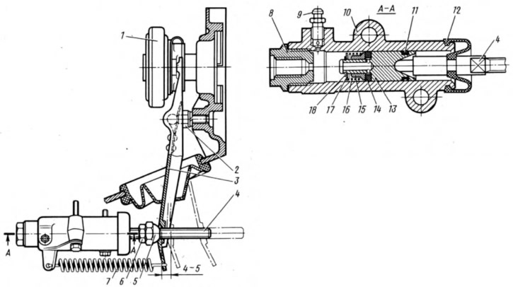
Pic. 62. Slave cylinder and clutch release fork:
1 - clutch release bearing; 2 - ball bearing; 3 - clutch release fork; 4 - pusher; 5 - adjusting nut; 6 - locknut; 7 - withdrawal spring; 8 - body plug; 9 - fitting for pumping; 10 - cylinder body; 11 - sealing ring; 72-protective cap; 13 - piston; 14 - sealant; 15 - plate; 16 - spring; 77 - support washer; 18 - retaining ring.
When the clutch is disengaged, the force from the pedal is 15 (see fig. 61) through the pusher 16 it is transmitted to the pistons and 6, which, moving in the main cylinder, compress the spring 23. In this case, the front sealing ring 20 closes the compensation hole 2, and the cylinder cavity is separated from the tank. Liquid under pressure through the tube and hose enters the cavity of the working cylinder, moving the piston (see fig. 62) and pusher 4. Turning relative to the ball joint 2, the fork moves the clutch release bearing, which through the bearing and thrust flange 14 (see fig. 60) bends the pressure spring on the support rings 17. The outer edge of the spring through the clamps takes the pressure plate 4 away from the driven disc 5 and the transmission of torque to the gearbox stops.
When the pedal is released, all parts return to their original position under the action of springs. O-ring 20 (see fig. 61) departs from the compensation hole 2 and restores communication between the cavities of the main cylinder and the tank.
From July 1972 to November 1978, the described cars were equipped with a clutch and brake pedal bracket, produced specifically for these models. Since December 1978, a bracket unified at the place of attachment has been installed, which made it possible to install a bracket with or without a vacuum booster on the same body. On unified brackets, a clutch pedal from a VAZ-2103 car is installed.
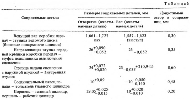
The dimensions of the main mating parts of the clutch and the limits of permissible wear are given in Table. 6.