




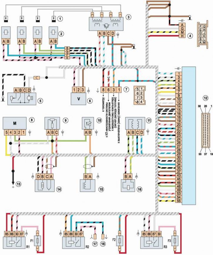
Electrical diagram of the engine control system with the January-5.1.3 controller: 1 - spark plugs; 2 - injectors; 3 - ignition module; 4 - diagnostic connector block; 5 - electric fuel pump with fuel level sensor; 6 - vehicle speed sensor; 7 - connection block with instrument panel wiring harness; 8 - mass air flow sensor; 9 - Throttle control sensor; 10 - coolant temperature sensor; 11 - idle speed control; 12 - Electronic control unit (ECU); 13 - to the positive terminal of the battery; 14 - oxygen concentration sensor; 15 - crankshaft position sensor; 16 - Evaporative Evaporative Blow-Off Solenoid Valve; 17 - wire connector to the mounting block (pin 6 of the Sh6 pad); 18 - block of wire to the "+" terminal of the electric fan; R1 - main relay; R2 - electric fan relay; R3 - electric fuel pump relay; F1 - Main relay circuit fuse (15A); F2 - ECU fuse (15A); F3 - Electric fuel pump circuit fuse (15A)