

Car suspension and shock absorber repair VAZ-21051

Description of the design of the front suspension
Front suspension 1 – bearings of a nave of a forward wheel; 2 - hub cap; 3 - adjusting nut; 4 - washer; 5 – a pin of a rotary fist; 6 - wheel hub; 7 - stuffing box; 8 - brake...
Front suspension 1 – bearings of a nave of a forward wheel; 2 - hub cap; 3 - adjusting nut; 4 - washer; 5 – a pin of a rotary fist; 6 - wheel hub; 7 - stuffing box; 8 - brake...

Determining the condition of the front suspension parts
Check of a condition of the rubber-metal hinge of the lever of a forward suspension bracket 1 - rubber bushing of the hinge; 2 - outer sleeve of the hinge; 3 – a nut of fastening...
Check of a condition of the rubber-metal hinge of the lever of a forward suspension bracket 1 - rubber bushing of the hinge; 2 - outer sleeve of the hinge; 3 – a nut of fastening...

Checking and adjusting wheel alignment
Checking and adjusting the angles of the front wheels is carried out on special stands in accordance with the instructions for the stand. Attention! Checking the wheel alignment...
Checking and adjusting the angles of the front wheels is carried out on special stands in accordance with the instructions for the stand. Attention! Checking the wheel alignment...

Checking and adjusting the clearance in the front wheel hub bearings
Checking the axial clearance of the front wheel hub bearings using tool 02.7834.9505 1 - indicator; 2 - bolt; 3 - bracket; 4 - wheel hub 1. To check the clearance, raise the front...
Checking the axial clearance of the front wheel hub bearings using tool 02.7834.9505 1 - indicator; 2 - bolt; 3 - bracket; 4 - wheel hub 1. To check the clearance, raise the front...

Replacing grease in front wheel bearings
1. Remove the decorative caps and loosen the wheel bolts. 2. Raise the front of the car and support it on stands, unscrew the bolts and remove the wheels. 3. Having unbent petals...
1. Remove the decorative caps and loosen the wheel bolts. 2. Raise the front of the car and support it on stands, unscrew the bolts and remove the wheels. 3. Having unbent petals...
Wheel balancing
Wheels are balanced on special stands according to the rules described in the instructions attached to the stands. After balancing, the maximum permissible unbalance of the wheel...
Wheels are balanced on special stands according to the rules described in the instructions attached to the stands. After balancing, the maximum permissible unbalance of the wheel...

Removal and installation of a forward suspension bracket
1. Install the car on a lift or inspection ditch; holding the end of the rod by the flats with the key A.57070, disconnect the upper end of the shock absorber. Remove the front...
1. Install the car on a lift or inspection ditch; holding the end of the rod by the flats with the key A.57070, disconnect the upper end of the shock absorber. Remove the front...

Disassembly and assembly of front suspension units
Left wheel suspension assembly fixed on a workbench for disassembly 1 - nuts for fastening the steering knuckle lever, caliper mounting bracket and protective cover to the...
Left wheel suspension assembly fixed on a workbench for disassembly 1 - nuts for fastening the steering knuckle lever, caliper mounting bracket and protective cover to the...

Front suspension arms — check
Checking the left lower arm 1 - mandrel for centering the ball joint; 2 - lower lever; 3 - hole for the mounting fingers of the device A.95716; 4 - fixture A.95716 for checking...
Checking the left lower arm 1 - mandrel for centering the ball joint; 2 - lower lever; 3 - hole for the mounting fingers of the device A.95716; 4 - fixture A.95716 for checking...

Front suspension ball joints — check
1. Make sure that the mudguards of the ball joints are intact. Breaks, cracks, delamination of rubber from metal fittings, traces of lubricant leakage are unacceptable. 2. Check...
1. Make sure that the mudguards of the ball joints are intact. Breaks, cracks, delamination of rubber from metal fittings, traces of lubricant leakage are unacceptable. 2. Check...

Rubber-metal joints of the front suspension — check
Pressing out the lower arm pivots 1 - the axis of the lever; 2 – hinge of the lever; 3 - mandrel Signs that require replacement of rubber-to-metal joints are described in...
Pressing out the lower arm pivots 1 - the axis of the lever; 2 – hinge of the lever; 3 - mandrel Signs that require replacement of rubber-to-metal joints are described in...

Front suspension steering knuckles — check
To check, install the steering knuckle 1 on the caliber 2 A.96008, clamped in a vice so that its surface under the wheel hub seal coincides with the caliber hole. Insert the two...
To check, install the steering knuckle 1 on the caliber 2 A.96008, clamped in a vice so that its surface under the wheel hub seal coincides with the caliber hole. Insert the two...

Front suspension springs — check
Checking the front suspension cross member 1 - a hole on the cross member for the mounting pins of the fixture; 2 - cross member; 3 - control bushings of the device; 4 - device...
Checking the front suspension cross member 1 - a hole on the cross member for the mounting pins of the fixture; 2 - cross member; 3 - control bushings of the device; 4 - device...

Replacing rubber-metal hinges of levers on a car
Scheme of pressing out the hinge of the lower arm using tool 02.7823.9500 1 - screw; 2 - nut; 3 - glass; 4 - lower lever; 5 - hinge; 6 - the axis of the lower arm Scheme of...
Scheme of pressing out the hinge of the lower arm using tool 02.7823.9500 1 - screw; 2 - nut; 3 - glass; 4 - lower lever; 5 - hinge; 6 - the axis of the lower arm Scheme of...

Description of the design of the rear suspension
Rear suspension 1 - spacer sleeve; 2 - rubber bushing; 3 - lower longitudinal rod; 4 - the lower insulating gasket of the spring; 5 - the lower support cup of the spring; 6 –...
Rear suspension 1 - spacer sleeve; 2 - rubber bushing; 3 - lower longitudinal rod; 4 - the lower insulating gasket of the spring; 5 - the lower support cup of the spring; 6 –...

Removal and installation of a back suspension bracket
Rear suspension parts 1 - lower longitudinal rod; 2 - rubber bushing; 3 – an arm of fastening of the bottom longitudinal bar to a body; 4 - spacer sleeve; 5 - upper longitudinal...
Rear suspension parts 1 - lower longitudinal rod; 2 - rubber bushing; 3 – an arm of fastening of the bottom longitudinal bar to a body; 4 - spacer sleeve; 5 - upper longitudinal...

Checking the technical condition of the rear suspension
1. Wash all parts thoroughly before checking. 2. Protect rubber parts, bushings and protective coatings from solvents when washing. Springs 3. Check the elastic characteristics of...
1. Wash all parts thoroughly before checking. 2. Protect rubber parts, bushings and protective coatings from solvents when washing. Springs 3. Check the elastic characteristics of...
Rear suspension bars
Examination 1. Check if the rods are deformed; if possible, correct them. 2. Check for cracks on the rear axle and body beam brackets; if cracks are found, repair the brackets. 3....
Examination 1. Check if the rods are deformed; if possible, correct them. 2. Check for cracks on the rear axle and body beam brackets; if cracks are found, repair the brackets. 3....
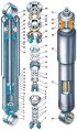
Front and rear shock absorbers
Front and rear shock absorbers 1 - lower eye; 2 – compression valve body; 3 - compression valve disks; 4 - throttle disk of the compression valve; 5 - compression valve spring; 6...
Front and rear shock absorbers 1 - lower eye; 2 – compression valve body; 3 - compression valve disks; 4 - throttle disk of the compression valve; 5 - compression valve spring; 6...
Checking shock absorbers on the stand
Shock Absorber Working Diagram A - effort during recoil; B - force during compression 1. To determine the performance of the shock absorber, check its working diagram on the dyno....
Shock Absorber Working Diagram A - effort during recoil; B - force during compression 1. To determine the performance of the shock absorber, check its working diagram on the dyno....
Dismantling and assembly of shock absorbers
1. After external washing, secure the shock absorber in a vise. Attention! Special jaws 67.7824.9513-001 are used to fix the shock absorber and its parts in a vice. 2. After...
1. After external washing, secure the shock absorber in a vise. Attention! Special jaws 67.7824.9513-001 are used to fix the shock absorber and its parts in a vice. 2. After...
Checking the technical condition of shock absorber parts
1. Rinse all parts with gasoline or kerosene and dry. 2. Carefully check that the parts comply with the following requirements: the disks of the compression and recoil valves, as...
1. Rinse all parts with gasoline or kerosene and dry. 2. Carefully check that the parts comply with the following requirements: the disks of the compression and recoil valves, as...
This section is available on russian, bulgarian, belarusian, ukrainian, serbian, croatian, romanian, polish, slovak, hungarian
More articles from other manuals on VAZ cars:
➠ Chassis: Car suspension VAZ-21011 (1974-1983)
➠ Chassis: Car suspension VAZ-21099 (1990-2004)
➠ Chassis: Suspension and wheels VAZ-2110 (1995-2007)
➠ Chassis: Wheel suspension VAZ-21213 (1994-2006)
➠ Chassis: Car suspension VAZ-21011 (1974-1983)
➠ Chassis: Car suspension VAZ-21099 (1990-2004)
➠ Chassis: Suspension and wheels VAZ-2110 (1995-2007)
➠ Chassis: Wheel suspension VAZ-21213 (1994-2006)
Share with friends:
- General information
- Operation and maintenance
- Power unit
- Engine repair
- Fuel system (carburetor)
- Fuel system (injector)
- Control system
- Cooling system
- Exhaust system
- Transmission
- Clutch
- Car gearbox
- Cardan gear
- Rear axle
- Chassis
- Front suspension
- Rear suspension
- Wheels and tires
- Steering
- Brake system
- Body
- Exterior
- Interior
- Doors and glass
- Ventilation and heating
- Electrical equipment
- Equipment and devices
- Headlights and lighting
- Engine electrics
- Electrical circuits
- General information
- Vehicle description
- Vehicle device
- Vehicle operation
- Maintenance
- Power unit
- Engine repair
- Cooling and lubrication system
- Supply system
- Transmission
- Clutch
- Car gearbox
- Cardan gear
- Rear axle
- Chassis
- Suspension and shock absorbers
- Steering
- Brake system
- Body
- Body elements
- Electrical equipment
- Engine electrics
- Equipment and devices
- General information
- Introduction to guide
- User manual
- Troubleshooting
- Power unit
- Engine repair
- Engine repair VAZ-2103
- Cooling system
- Lubrication system
- Power and exhaust system
- Fuel injection
- Transmission
- Clutch
- Car gearbox
- Cardan gear
- Rear axle
- Chassis
- Suspension and shock absorbers
- Steering
- Brake system
- Body
- Exterior
- Interior
- Doors and windows
- Electrical equipment
- Equipment and devices
- Engine electrics
- Ignition system
- Electrical circuits
VAZbook.ru © 2017 · Mobile version · Contact with administration · Sitemap: EN BG BY UA RS HR RO PL SK HU · Site search · News and articles
VAZ-1111 · VAZ-11113 · VAZ-2101 · VAZ-21011 · VAZ-2104 · VAZ-2105 · VAZ-21051 · VAZ-2106 · VAZ-21061 · VAZ-2107 · VAZ-21099 · VAZ-2109 · VAZ-2108 · VAZ-2110 · VAZ-2112 · VAZ-2114 · VAZ-2115 · VAZ-2121 · VAZ-21213 · VAZ-21214 ·