




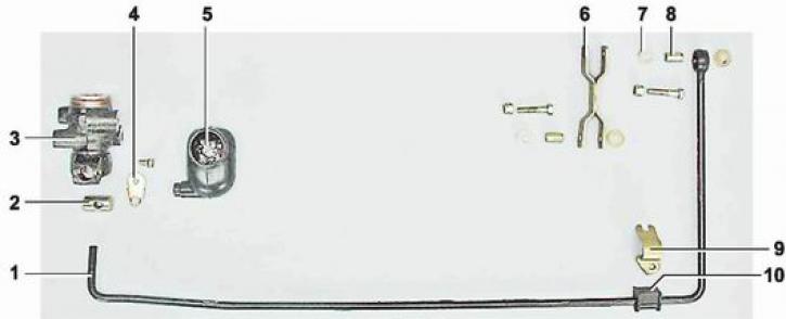
Pressure regulator drive parts: 1 - regulator drive lever (2101-3512122); 2 - lever axis (2101-3512116); 3 - pressure regulator (2101-3512010); 4 - lever lock plate (2101-3512117); 5 - protective cover (2101-3512118); 6 - drive lever rod (2101-3512132); 7 - polymer bushing of the lever stand (2101-3512136); 8 - spacer sleeve (2101-3512135); 9 - lever mounting bracket (2101-3512128); 10 - Drive lever bushing (2101-3512125)
To complete the work you will need an assistant and a special key by 10 mm for brake pipes, transparent vinyl tube of suitable diameter, container for draining brake fluid, fresh brake fluid (see "Operating fluids").
Examination
1. Place the vehicle on an inspection pit or overpass (see "Preparing a car for maintenance and repair").
2. Clean the regulator and protective cover from dirt.
3. Remove the rubber protective cover from the regulator and remove the grease from the point where the piston contacts the lever axis.
4. The assistant presses the brake pedal with a force of 70-80 kgf, at this moment we observe the movement of the protruding part of the regulator piston. If the piston movement relative to the regulator body is 0.5-0.9 mm, then the regulator is in good working order. If the piston does not move when pressing the pedal, we replace the pressure regulator.
5. Make sure there is no brake fluid leakage between the regulator body and the piston.
6. Apply waterproof grease to the end of the lever and the protruding part of the piston and place 5-6 g of the same grease in the rubber boot.
7. Install the cover on the pressure regulator.
Removal
To make the work easier, disconnect the right shock absorber from the rear axle bracket and move it to the side (see "Rear shock absorber - replacement").
1. With a socket wrench by 10 mm we unscrew the nut of the bolt that secures the pressure regulator drive lever to the rod, holding the bolt from turning with a wrench of the same size.
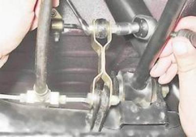
2. Remove the bushings from the hole in the lever eye.
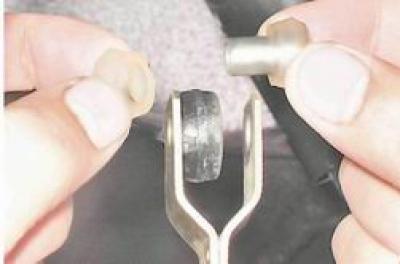
3. Key by 10 mm we unscrew the two nuts of the bracket that secures the lever to the body and remove the bracket.
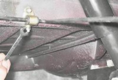
4. With a socket wrench by 13 mm using an extension, unscrew the three nuts securing the regulator bracket to the body and the two bolts securing the regulator to the bracket.
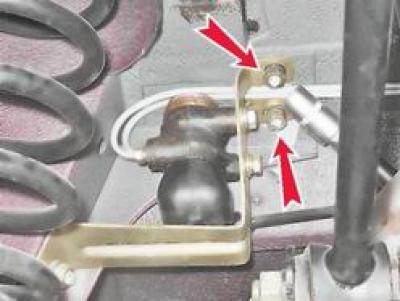
5. Remove the bracket.
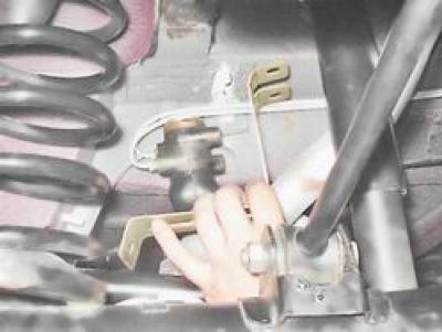
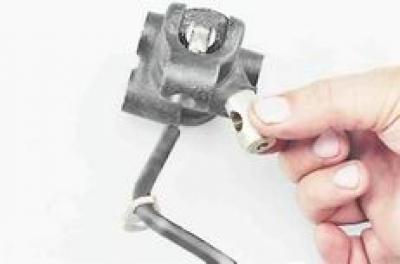
6. With a special key by 10 mm for the brake pipes, unscrew the two fittings that attach the pipes to the regulator and move them to the side.
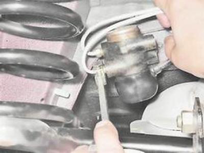
7. Remove the pressure regulator assembly with the drive lever.
8. After moving the protective cover, unscrew it with a key by 8 mm bolt securing the lever lock plate to the regulator body.
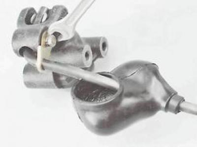
9. Disconnect the lever from the regulator and remove the lever axle from it.
Installation
1. Install the pressure regulator in reverse order.
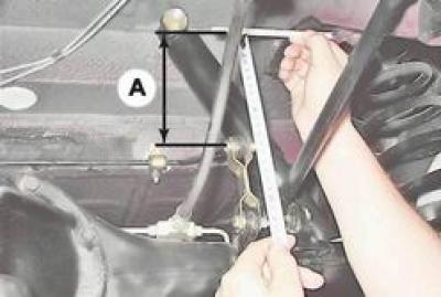
2. Before tightening the regulator mounting bolts, set the distance A = 140+5 mm from the end of the regulator lever to the horizontal platform of the body side member.
3. Remove the rubber protective cover from the regulator.
4. By changing the position of the regulator relative to the upper slot in the bracket, we achieve light contact of the lever with the regulator piston.
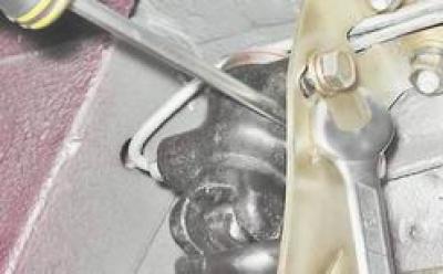
5. In this position, tighten the bolts securing the regulator to the bracket.
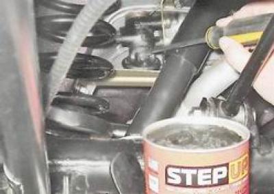
6. Apply plastic waterproof grease to the end of the lever and the protruding part of the piston and place 5-6 g of this grease in the rubber boot.
(The article is copied from the website VAZBOOK)
7. Install the cover on the pressure regulator.
8. Bleed the brake hydraulic system (see "Hydraulic brake drive - bleeding and replacing brake fluid").