




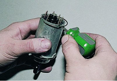
Using a thin screwdriver, remove the retaining ring.
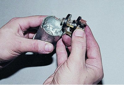
We remove the contact part from the switch housing.
We assemble and install the switch in the reverse order, taking into account that...
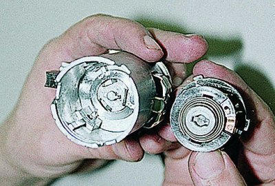
...the grooves in the switch housing and the protrusions of the contact part have different widths, so the contact part is installed in the switch in only one position.
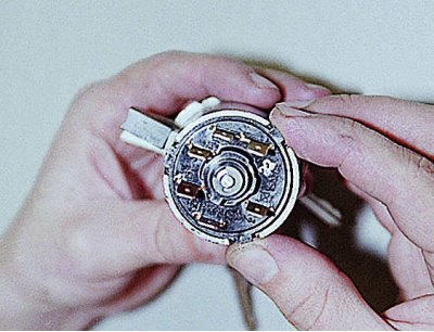
To avoid guessing during assembly, use terminals "15" and "30" as a guide, which should be opposite the locking rod.
Switching the ignition switch terminals
| Key position | Contacts below voltage | Switched circuits |
| 0 (Disabled) | 30 and 30/1 | — |
I (Ignition) | 30-INT | Outdoor lighting. Windscreen and headlight wipers and washers |
| 30/1-15 | Generator excitation winding. Ignition system. Carburetor pneumatic valve control system. Direction indicators. Control devices. Heater. Rear window heating. Reverse light | |
II (Starter) | 30-INT | See position I |
| 30/1-15 | See position I | |
| 30-50 | Starter | |
| III (Parking) | 30-INT | See position I |