




Removal
1. Prepare the vehicle for operations (see "Preparing a car for maintenance and repair").
2. Disconnect the wire from the negative terminal of the battery (see "Battery - Removal and Installation").
3. Remove the steering column shaft covers (see "Steering shaft covers - removal and installation").
4. Disconnect the wiring harness connector from the ignition switch contacts.
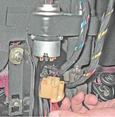
5. Insert the key into the ignition switch. Turn the key to position "0" and slightly turn the steering wheel to the right and left to unlock the steering shaft.
6. Using a Phillips screwdriver, unscrew the two screws securing the lock to the steering shaft bracket.
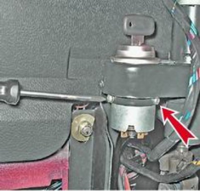
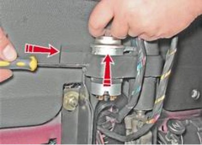
7. Using a screwdriver or other suitable tool, push the lock retainer through the side hole in the bracket and remove the lock from the bracket hole.
Examination
To complete the work you will need a multimeter.
To check the contact group alternately (in accordance with table 13.16) connect the ohmmeter probes to the ignition switch terminals and check the switching of the contacts in different key positions. The resistance of a serviceable contact group should tend to zero. If the resistance is greater than zero, the contacts are dirty or burnt.
Table 13.16. Ignition switch contacts switching
|
Position of the key in the ignition switch |
Contacts under voltage |
Switched circuits |
|
0 |
30 and 30/1 |
- |
|
I |
30-INT |
Exterior lighting, windshield wipers and washers, tailgate wipers and washers |
|
30/1-15 |
Generator excitation winding, ignition system, carburetor pneumatic valve control system, power supply and control system (for injection engine), direction indicators, control instruments, heater, heated rear window, reversing lights |
|
|
II |
30-INT |
See position I |
|
30/1-15 |
See position I |
|
|
30-50 |
Starter |
|
|
III |
30-INT |
See position I |
Replacing the contact group
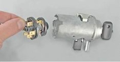
1. Using a screwdriver, remove the retaining ring from the groove in the lock body.
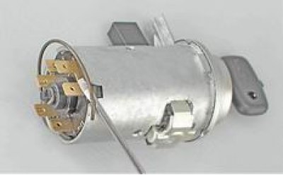
2. Remove the contact group from the lock body.
Assembly
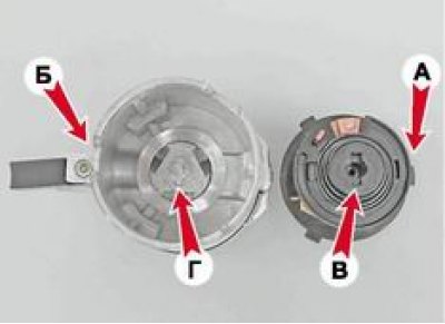
1. Install the contact group of the lock, aligning the wide protrusion A on the contact group with the wide groove B on the lock body and at the same time aligning the groove B at the end of the contact group axis with the end protrusion G of the lock axis.
2. Installation of removed parts is performed in reverse order.