

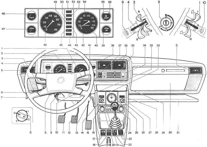
Pic. 4. Controls and instrumentation:
1 - switch lever for windshield wipers and washers of the windshield and block headlights; 2 - sound signal switch; 3 - turn signal switch lever; 4 - headlight switch lever; 5 - side nozzles of the ventilation and interior heating system; 6 - headlight hydraulic corrector; 7 - engine hood lock drive lever; 8 - cartridge for connecting a portable lamp; 9 - ignition switch; 10 - alarm switch; 11 - clutch pedal; 12 - brake pedal; 13 - heater cover lever; 14 - instrument lighting switch; 15 - accelerator pedal; 16 - a place for a radio receiver; 17 - outdoor lighting switch; 18 - rear fog lights switch. 19 - parking brake lever; 20 - reserve control lamp; 21 - control lamp for turning on the heating of the rear window; 22 - rear window heating switch; 23 - plug; 24 - gear lever; 25 - hours; 26 - cigarette lighter; 27 - reserve control lamp; 28 - control lamp of the fluid level in the hydraulic brake reservoir; 29 - ashtray; 30 - glove box; 31 - storage shelf; 32 - insert; 33 - carburetor air damper control handle; 34 - plug; 35 - block of levers for controlling the ventilation and heating system; 36 - central nozzles of the interior ventilation system; 37 - three-position heater electric fan switch; 38 - instrument cluster; 39 - voltmeter; 40 - speedometer; 41 - handle for resetting the daily mileage counter; 42 - summing counter of the distance traveled; 43 - control lamp for switching on the high beam; 44 - control lamp for turning on the parking brake; 45 - control lamp of insufficient oil pressure in the engine lubrication system; 46 - tachometer; 47 - liquid temperature gauge in the engine cooling system; 48 - econometer; 49 - control lamp for turning on side lights; 50 - battery charge control lamp; 51 - block of control lamps; 52 - control lamp of direction indicators; 53 - carburetor air damper control lamp; 54 - daily run counter; 55 - fuel reserve control lamp; 56 - fuel gauge.
1 - switch lever for windshield wipers and washer and headlights. It is energized when the ignition key is in position I or III. With lever position:
- I - windshield wiper off
- II - windshield wiper works intermittently
- III—windshield wiper operates continuously
By moving the lever towards you, the windshield washer is turned on, and if the high or dipped headlights are on, then the wipers and washers of the block headlights are turned on at the same time.
2 - horn switch. It is constantly under pressure.
3 — the lever of the switch of indexes of turn. It is energized when the ignition key is in position I. When the lever is moved to position «A» right turn indicators are switched on «IN» - Left turn indicators. When the car goes straight after turning, the lever automatically returns to its original position. This operation can also be performed manually.
4 - headlight switch lever. If the outdoor lighting switch 17 is turned on to the second fixed position, the ignition key is in position I or III, and the switch lever is in position:
- I - dipped headlights on
- II - high beam headlights on
High beam headlights can also be turned on when the exterior light switch is off by moving the lever towards you along the steering column. When released, the lever returns to its original position automatically.
5 - side nozzles of the ventilation and interior heating system.
6 - headlight hydraulic corrector. It is installed on a part of produced cars. By turning the handle, depending on the load of the car, the angle of inclination of the headlight beam is adjusted. Handle positions:
- «0» - one driver;
- «1» - all places are occupied;
- «2» — All seats are occupied + cargo in the trunk to full load on the rear axle;
- «3» - one driver + load up to full load on the rear axle.
For other loading options without exceeding the useful mass, the positions of the handles are selected in such a way that the illumination of the road in the low beam headlights is within the normal range and drivers of oncoming vehicles are not blinded.
Cars without hydrocorrector for headlights in the variant version can be equipped with block headlights with set screws 4 (see fig. 65). In this case, with the vehicle fully loaded, turn the set screws to the far right.
7 - engine hood lock drive lever.
8 - cartridge for connecting a portable lamp.
9 - ignition switch. At key position:
- «0» - everything is off, the anti-theft device is not included;
- «I» - the ignition is on;
- «II» — the starter is included;
- «III» - the ignition is off, with the key removed, the anti-theft device is turned on.
To turn off the anti-theft device, insert the key into the ignition switch and, while slightly turning the steering wheel to the right and left, turn the key to position «0».
10 - alarm switch. When the button is pressed, the flashing light of all direction indicators and the control lamp in the button itself turn on. The alarm is turned off when the button is pressed again.
11 - clutch pedal.
12 - brake pedal.
13 - heater cover lever.
14 - instrument lighting switch. It is energized if the outdoor lighting switch 17 is on. Turning the handle turns on the instrument lighting and adjusts its brightness.
15 - accelerator pedal.
16 - a place for a radio receiver.
17 - outdoor lighting switch. When the upper shoulder of the key is pressed to the first fixed position, the parking lights are turned on, and when pressed to the second fixed position, the headlight circuits are additionally energized.
18 - rear fog lights switch. The lights are turned on by pressing the upper shoulder of the key when the headlights are on. At the same time, the orange light lamp in the key itself signals the inclusion of the lights and at the same time illuminates the key.
19 - parking brake lever. Moving the lever up activates the rear wheel brake pads. To return the lever to its original position, press the button on the end of the lever handle.
In case of emergency, the parking brake can be used while the vehicle is moving to slow down, or it can be used simultaneously with the service brakes.
20 - backup control lamp. In the variant, if the car is equipped with seat belts with signaling about unfastened driver belts, a warning lamp is installed «Fasten seat belts».
21 - control lamp for turning on the rear window heating. Lights up in orange if the rear window heating is switched on by switch 22.
22 - rear window heating switch. Rear window heating is activated by pressing the upper shoulder of the key with the ignition on. At the same time, the orange light lamp illuminates the key.
23 - plug.
24 - gear lever. The gearshift pattern is printed on the lever handle.
25 - hours. To move the arrows, pull the handle towards you and turn it counterclockwise.
26 - cigarette lighter. To use, press the button of the cartridge, which after about 15 seconds will automatically return to its original position, ready for use. When the outdoor lighting switch 17 is turned on and the instrument lighting switch 14 is turned on, a special lamp illuminates the cigarette lighter socket.
27 - backup control lamp.
28 - liquid level control lamp. in the hydraulic brake reservoir. The lamp lights up with a constant red light if the liquid level in the tank has dropped below the permissible limit due to fluid consumption or due to system damage. To check the serviceability of the lamp itself, it lights up if the parking brake lever is raised.
29 - ashtray.
30 - glove box.
31 - storage shelf.
32 - insert.
33 - carburetor air damper control knob. Used to start a cold engine. When the handle is pulled out, the carburetor air damper is closed, which is indicated in the instrument cluster by the corresponding control lamp.
34 - plug.
35 - block of levers for controlling the ventilation and heating system.
36 - central nozzles of the interior ventilation system.
37 - three-position heater fan switch. It is energized when the ignition is on. When the lower arm of the key is pressed to the first fixed position, the low speed of the electric fan is switched on, and when the lower arm is pressed all the way, the high speed is switched on.
38 - instrument cluster.
39 - voltmeter. A device that controls the voltage of the vehicle's on-board network. With the ignition on and the engine off, the voltmeter shows the voltage at the battery terminals, and with the engine running, the voltage at the generator terminals. The arrow of the device with the engine running in the red zone at the beginning of the scale indicates the discharge of the battery due to a weak tension of the generator drive belt or a malfunction of the generator itself, and in the white zone of the scale it indicates an unsteady charge-discharge mode. The arrow of the device in the green zone indicates normal voltage, and the transition to the red zone at the end of the scale indicates overcharging of the battery due to a malfunction of the generator.
40 - speedometer.
41 - handle for resetting the daily mileage counter. The counter is set to zero when the vehicle is stationary by turning the knob counterclockwise.
42 - summing counter of the distance traveled.
43 - control lamp for switching on the high beam. The lamp lights up blue when the high beam headlights are switched on.
44 - control lamp for turning on the parking brake. The lamp lights up with a red flashing light when the ignition is on and the parking brake lever is raised. If the car is equipped with front brake pads with pad wear indicators, then when the pads are worn, the lamp lights up with a constant red light.
45 - control lamp of insufficient oil pressure in the engine lubrication system. The lamp lights up red when the ignition is switched on. After starting the engine, when the crankshaft speed rises above the minimum, the lamp should go out.
46 - tachometer. An electronic type device that indicates the speed of the engine crankshaft. The yellow zone of the scale indicates the mode of operation of the engine with a high crankshaft speed, the red zone of the scale indicates modes that are dangerous for the engine.
47 - fluid temperature gauge in the engine cooling system. The arrow in the green zone of the scale indicates the normal temperature of the coolant. The transition of the arrow to the red zone of the scale indicates overheating of the engine. In this case, check the tension of the alternator drive belt, and if its tension is within normal limits, check the cooling system.
48 - econometer. A device that helps the driver, when driving out of town, to select the engine speed and the corresponding gear in the gearbox, the most economical driving mode in terms of fuel consumption. When driving in economy mode, the pointer of the device is in the green zone of the scale.
49 - control lamp for turning on the parking lights. The lamp lights up green if the outdoor light switch 17 is turned on.
50 - battery charge control lamp. The lamp lights up red when the ignition is switched on and goes out immediately after starting the engine. If the lamp is on when the engine is running, this indicates a weak tension of the generator drive belt or a malfunction of the generator itself.
51 - a block of control lamps.
52 - control lamp of direction indicators. When the ignition is on, the lamp lights up in green flashing light, if the lever 3 is moved to the position «A» or «IN». If one of the direction indicator lamps fails, the control lamp lights up constantly.
53 - carburetor air damper control lamp. The lamp lights up in orange if the ignition is on and the carburetor choke control knob 33 is pulled out.
54 - daily mileage counter.
55 - fuel reserve control lamp. Lights up red if there is less than 4-6.5 liters of gasoline left in the fuel tank.
56 - fuel gauge.