
At the ends of handles, keys, filters of control lamps, symbolic images are placed to remember their purpose.
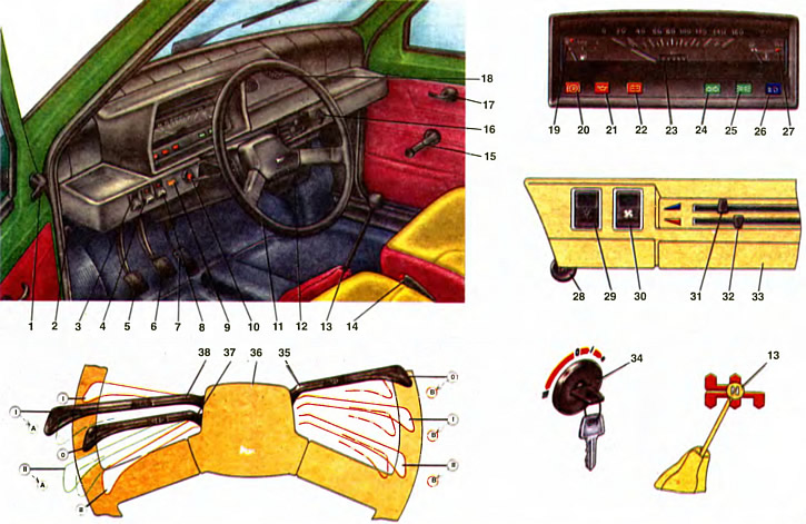
1. Outside mirror adjustment knob. 2. The lever of the hood lock. 3. Rear window wiper and washer switch. 4. Rear window heating switch. 5. Clutch pedal. 6. Brake pedal. 7. Carburetor throttle control pedal. 8. Rear fog light switch. 9. Control lamp for covering the air damper of the carburetor. 10. Alarm switch. 11. Steering wheel. 12. Heater casing cover. 13. Gear lever. 14. Parking brake lever. 15. Power window handle. 16. Cigarette lighter. 17. Door lock handle. 18. Rotary deflectors. 19. Fuel gauge in the tank with fuel reserve control lamp. 20. Parking brake and brake fluid level warning lamp. 21. Oil pressure warning lamp. 22. Battery discharge indicator lamp. 23. Speedometer. 24. A control lamp of indexes of turn. 25. Control lamp for outdoor lighting. 26. Control lamp high beam headlights. 27. Coolant temperature gauge. 28. Carburetor choke control knob. 29. Outdoor lighting switch. 30. Heater fan motor switch. 31. Air damper control lever. 32. Control lever for heater valve. 33. Ashtray. 34. Ignition switch. 35. Switch lever for windshield wiper and washer. 36. Sound signal switch. 37. The lever of the switch of indexes of turn. 38. Headlight switch lever.
Governing bodies
Gear lever 13. Move to the desired position according to the scheme engraved on its handle. The neutral position of the lever is determined by its free movement to the left, while the lever tends under the action of the spring to become in the position of switching on III and IV gears.
When moving the lever to the left and right, the gears are selected, and when turning on the axis (moving the handle back and forth) gear engagement.
It should be remembered that the inclusion of reverse gear should be done only after the car has come to a complete stop. When reverse gear is engaged, the reversing lamps in the rear lights are simultaneously turned on, signaling the vehicle is moving backwards.
Lever 14 parking brake serves to brake the car in the parking lot or on the rise. By moving the lever up to failure, the rear wheel brake pads are activated. At the same time, the control pump 20 lights up with a flashing red light.
In case of emergency, the parking brake can be used as an emergency while the vehicle is moving. To return the lever to its original position, press the button on the end of the lever handle.
Pedal 7 carburetor throttle control. Starting a cold engine is carried out without pressing the pedal. It is not recommended to press the pedal after starting a cold engine until the engine warms up and starts to work steadily, without interruptions. And vice versa, if you need to start a hot engine, then you need to press the pedal about a third of its travel, and after starting, as soon as the engine starts to work without interruption, gradually release it.
Switch 34 (lock) ignition. The key in the lock can occupy four positions:
- 0 - everything is off, except for circuits that are energized regardless of the key position. These are the power supply circuits for the sound signal and alarm, brake light, cigarette lighter, external and internal lighting (except for headlights). The key cannot be removed from the lock, the anti-theft device is not included.
- I - the ignition is on and the power supply to all consumers of electricity, except for the starter circuit. It is used before starting the engine and while driving. The key cannot be removed from the lock, the anti-theft device is not included.
- II - the starter and ignition are on. Voltage is also supplied to the power circuits of direction indicators, control devices and windshield wiper. Used to engage the starter and start the engine. The key is not fixed in the lock and cannot be removed, the anti-theft device is not included.
- III - everything is off, except for circuits that are energized regardless of the position of the key (see position 0). With the key removed, the anti-theft device is activated. Used at a stop or parking lot outside the garage. To turn off the anti-theft device, insert the key into the lock and, slightly turning the steering wheel to the right and left, turn the key to position 0.
Pedal 6 brake. Serves for braking the car, which should be smooth and long. You should get used to considering the brakes as an emergency system, which will reduce tire wear and fuel consumption, and create a comfortable ride for passengers. Sharp intensive braking by a brake pedal to apply only in exceptional cases.
Handle 28 carburetor choke control pushed in to the stop when the damper is fully opened and is fixed in any intermediate position when the engine warms up. When the handle is pulled out to failure, the damper closes completely. The full cover of the carburetor air damper is used when starting a cold engine to enrich the combustible mixture. After warming up, do not forget to open the damper by pushing the handle. When the handle is pulled out, the control lamp 9 of the air damper cover lights up.
Clutch pedal 5 serves to actuate the mechanical drive for disengaging the clutch.
Steering wheel 11 serves to set the direction of movement for the vehicle. Its design provides visibility of all control devices.
Control devices
All control devices are assembled in the instrument cluster and work only when the ignition is on (except for the speedometer). The speedometer works while the car is moving.
Speedometer 23 with a total counter of the distance traveled by the car in kilometers. Red dots on the scale near the numbers 40, 60 and 100 indicate speeds that are not recommended to be exceeded when driving in 1st, 2nd and 3rd gears, respectively.
Pointer 27 coolant temperature in the engine cooling system. The transition of the arrow to the red field of the scale indicates excessive heating of the engine. In this case, immediately reduce the engine speed to a minimum (without stopping him). If the overheating persists, check the operation of the cooling fan and thermostat.
Pointer 19 fuel level in the tank with a fuel reserve warning lamp that lights up orange if there are 4... 6.5 liters of gasoline left in the fuel tank.
Pilot lamp 20 (red) parking brake and brake fluid level lights up with a flashing light when the parking brake lever 14 is moved up. The same lamp lights up constantly when the liquid level in the tank drops below the permissible limit due to fluid consumption or due to system damage.
Pilot lamp 21 (red) insufficient oil pressure in the engine lubrication system, it lights up when the oil pressure drops below the permissible value.
Pilot lamp 22 (red) battery discharge lights up when the ignition is switched on and goes out after the engine is started. If the lamp is lit while the engine is running, this indicates a malfunction in the battery charging system or a weak tension (cliff) generator drive belt.
Pilot lamp 24 (green) turning on the direction indicators lights up with a flashing light when the turn signal is turned on.
Pilot lamp 25 (green) turning on side light lights up when the outdoor lighting is turned on.
Pilot lamp 26 (blue) turning on high beam headlights lights up at the same time as the high beam headlights are switched on. A burning lamp reminds the driver of the need to timely turn off the high beam when meeting with another car, entering illuminated sections of the road, and also in all cases when it can blind other drivers. If you are following the car in front and do not intend to overtake it, turn on the dipped beam and, keeping a proper distance from it, you will drive safely without disturbing the person in front of you.
Pilot lamp 9 (orange) cover for the carburetor air damper.
Controls for lighting and signaling devices
Switch 36 horn is triggered by pressing a plastic pad in the steering wheel hub that covers the contact parts of the switch.
Switch 29 outdoor lighting. When the lower arm of the key is pressed to the first fixed position, the parking lights and instrument lighting are turned on, and when pressed to the second position, the headlight circuits are additionally energized.
Alarm switch 10. When the button is pressed, the flashing light of all direction indicators and the control lamp in the button turns on. Pressing the button again turns off the alarm.
Switch 8 rear fog light. The rear fog light is turned on by pressing the switch. At the same time, the orange control lamp in the switch button lights up.
Lever 37 turn signal switch has three positions:
- 0 - direction indicators are off;
- I — indicators of the right turn are included;
- II - left turn indicators are on.
Lever 38 headlight switch functions as follows (with the ignition on):
- I - dipped headlights on. if the headlights are switched on by switch 29;
- II - high beam is on, if headlights are turned on with switch 29. At the same time, the switching on of the main beam is signaled by a blue indicator lamp in the combination of lights.
A - (lever pulls back) the high-beam headlight signaling is on, regardless of the position of the switch button 29.
Used to briefly turn on the high beam to illuminate the road or give a light signal to pedestrians and drivers. When released, the lever returns to its place.
Driver's seat equipment
Lever 35 wiper and washer switch windshield (right under the steering wheel) may take the following positions:
- 0 - everything is disabled;
- I - intermittent operation of the windshield wiper is on;
- II - continuous operation of the windshield wiper is on;
- IN - (to myself) the windshield washer is turned on for the time the lever is held in this position (non-fixed lever position).
Switch 3 wiper and washer rear window. When you press the lower shoulder of the key to the first fixed position, the cleaner is turned on, and to the second (not fixed position) — and a rear window washer.
Switch 4 rear window heating. The glass heating is switched on by pressing the button. At the same time, the orange control lamp in the key lights up.
Interior and exterior mirrors designed to monitor the road behind the car. The interior mirror is fixed in two positions for day and night. If the headlights of a car coming behind interfere, the lever changes the angle of the mirror. The outside mirror is adjusted by handle 1 from inside the car.
sun visors are hinged, which allows them to be installed either at the top of the windshield or parallel to the door windows, depending on the direction of the sun's rays.
Cigarette lighter 16 activated by pressing the handle of the cartridge to failure. The cigarette lighter coil heats up in about 15 seconds. After heating, the cartridge automatically returns to its original position, ready for use.
Ashtray 33 opens onto itself behind the protruding side of its front wall, and for cleaning it is removed from the nest by pressing the spring stop inside the ashtray.
Lever 2 bonnet lock drive opens the hood latch by pulling it towards you.
Headrests on the front seats are height adjustable and held in position by spring clips.
Slider latch lever The front seat is located on the right side of the seats. To move the seat forward and backward, pull the lever up.
Backrest adjustment handles The front seats are located at the base of the backrest, on the side of the doors. The coarse adjustment handle is made in the form of a lever. By lifting this handle up, you can turn the backrest to the desired position. For example, tilt forward for the convenience of boarding passengers in the back seat, or, conversely, recline the back to arrange a place to relax. By turning another knob, you can smoothly adjust the inclination of the backrest within a small range.
Ceiling light the interior is switched on and off by a switch built into it.
The interior ventilation and heating control system includes the following elements:
The switch 30 of the heater fan motor is used to turn on the electric fan to the appropriate mode if it is necessary to increase the amount of air entering the passenger compartment.
Heater housing cover 12 designed to direct heated air to the feet of the driver and passengers.
Lever 32 control valve heater regulates the flow of hot fluid from the engine into the heater core and thus the temperature of the air passing through the heater core.
Lever 31 for controlling the cover of the air intake hatch regulates the amount of air passing through the heater. When the lever is moved to the leftmost position, the lid closes; by moving the lever to the right, the lid opens and outside air flows into the vehicle interior for ventilation or for heating in winter.
Rotary deflectors 18 change the direction of air flow from the heater.