




The air entering the engine cylinders is cleaned of dust by the air filter.
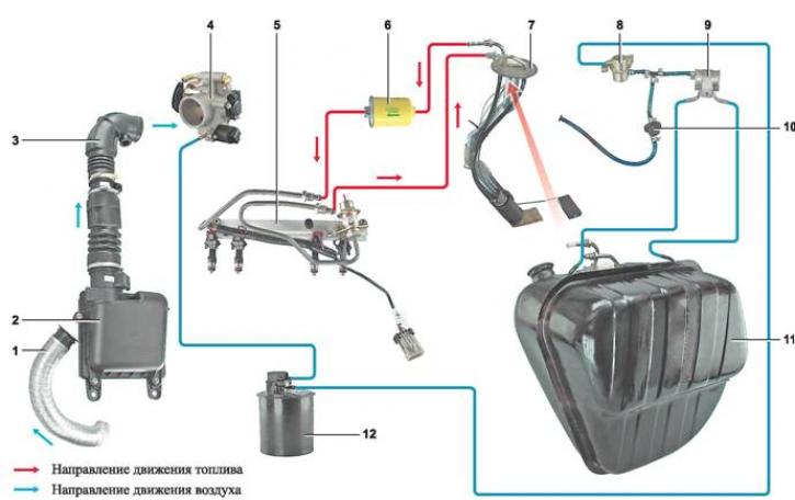
Elements of the fuel system of an injection engine: 1 - air intake; 2 - air filter housing; 3 - air supply hose to the throttle body; 4 - throttle body with idle speed control; 5 - fuel rail; 6 - fuel filter; 7 - Electric fuel pump with fuel level indicator sensor; 8 - gravity valve; 9 - bypass valve; 10 - safety valve; 11 - fuel tank; 12 - adsorber
Air filter housing installed in the engine compartment on three rubber supports. The filter element is replaceable and made of special paper. To prevent contaminated air from being sucked into the intake tract, there is a sealing edging on top of the element. The filter cover is removable to replace the filter element. Cleaned air passes through the mass air flow sensor along the sleeve to the throttle valve.
Throttle body mounted on the studs of the receiver flange. The throttle valve regulates the amount of air entering the engine cylinders. The valve is driven by the gas pedal, cable-operated. The valve rotates on an axis in the housing. A channel for coolant is made in the throttle valve housing. The channel is connected to the cooling system by rubber hoses. Circulation of coolant through the throttle valve housing prevents freezing of the internal air cavities of the housing in winter. The housing has fittings for connection to the adsorber and the engine crankcase ventilation system.
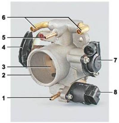
Throttle body: 1 - nipple for connection to the adsorber; 2 - throttle body pipe; 3 - throttle valve; 4 - throttle actuator sector; 5 - crankcase gas outlet fitting; 6 - nipples for connection to the engine cooling system; 7 - throttle position sensor; 8 - idle speed controller
Idle speed control valve - is a shut-off valve driven by an electric stepper motor. The regulator is mounted on the throttle body under the throttle position sensor.
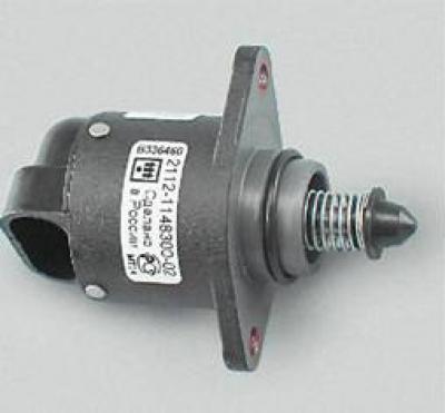
Idle speed control valve
Based on the signal from the electronic control unit (ECU), the regulator changes the cross-section of the additional air supply channel, thereby adjusting the crankshaft speed at idle.
Fuel tank - steel, lead-lined from the inside, welded from two stamped parts. The tank is located in the trunk on the right side. The fuel tank filler neck is closed with a plug and is brought out into the filler neck niche on the right wing.
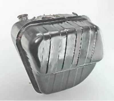
Fuel tank
Fuel is supplied from the tank electric fuel pump, combined with the fuel level indicator sensor. A mesh filter is installed on the pump inlet pipe, trapping large particles of dirt that have entered the fuel tank along with gasoline. The pump is switched on by the ECU command. A serviceable pump should develop a pressure of at least 3.2 bar (320 kPa).
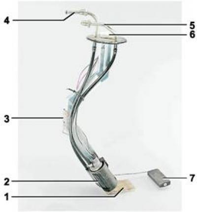
Electric fuel pump: 1 - receiving mesh filter; 2 - fuel pump; 3 - fuel level indicator sensor; 4 - supply pipe; 5 - drain pipe; 6 - Electrical connector block; 7 - sensor float
From the pump, the fuel flows through the fuel line to the fuel filter for more thorough cleaning.
Fuel filter - mounted on the engine compartment bulkhead bracket and built into the pipeline between the electric fuel pump and the fuel rail. The filter element is paper and is housed in a non-separable metal housing. An arrow is applied to the filter housing, which shows the direction of fuel movement in the filter. Cleaned fuel flows through the fuel pipe into the fuel rail.
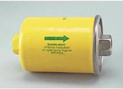
Fuel filter
Fuel rail is a hollow bar through which fuel is supplied to four injectors fixed to it. The connections of the ramp with the injectors, pressure regulator and fuel pipes are sealed with rubber rings. The ramp is fixed to the intake manifold with two screws. At the top of the ramp (next to the third cylinder injector) there is a fitting for monitoring fuel pressure, covered with a protective cap.
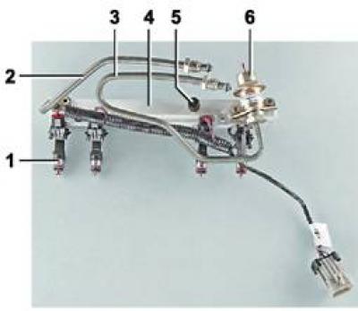
Fuel rail assembly: 1- nozzle; 2 - supply pipe; 3 - drain pipe; 4 - fuel rail; 5 - nipple with a spool valve for checking the working pressure (closed with a threaded cap); 6 - fuel pressure regulator
Fuel pressure regulator - a bypass valve that maintains the operating pressure in the fuel system within 2.8-3.2 bar (280-320 kPa) depending on the vacuum in the receiver, necessary for the correct operation of the engine. The regulator is installed on the fuel rail.
Nozzle is fixed to the ramp with a metal retainer and is an electromechanical valve, when an electrical impulse is supplied to it from the ECU, the nozzle holes open and fuel is supplied (injected) into the engine intake manifold. The amount of fuel supplied depends on the pulse duration.
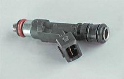
Nozzle
Attention! The injectors installed on cars may differ in overall dimensions and characteristics. When replacing, install an injector identical to those installed on your car.
In accordance with the environmental requirements of EURO II, the car is equipped fuel vapor recovery system. The system consists of an adsorber with a purge solenoid valve (installed in the engine compartment), safety and relief valves (installed in the fuel tank niche), connecting tubes and hoses. Fuel vapors from the tank enter the adsorber through the bypass and gravity valves.
The safety valve, which has an outlet to the atmosphere, regulates the pressure of fuel vapors in the tank.
The gravity valve is installed in the vapor recovery system line and prevents fuel from leaking out of the tank when the vehicle rolls over.
Adsorber has three branches. Through the branch "TANK" (the designation is applied to the body) the fuel vapors entering the adsorber when the engine is not running are absorbed and retained by the activated carbon. The second branch pipe, marked "AIR", is connected to the atmosphere, and the third (purge solenoid valve pipe) - connected by a hose to the throttle body fitting. After starting the engine (at a coolant temperature above 75°C, vehicle speed over 10 km/h and throttle opening more than 4%), the ECU sends a signal to open the purge valve of the adsorber, which communicates the cavity of the adsorber with the throttle body. In this case, the adsorber is purged - fuel vapors are mixed with air and then fed through the throttle body, receiver and intake manifold into the combustion chambers. The greater the air consumption of the engine (when crankshaft speed increases), the more intensive the blowing is.
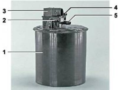
Adsorber: 1 - adsorber body; 2 - branch pipe for connecting the internal cavity of the adsorber with the atmosphere; 3 - purge valve of the adsorber; 4 - valve connecting pipe; 5 - adsorber connecting pipe