




Schematic diagram of the hazard warning and direction indicator system
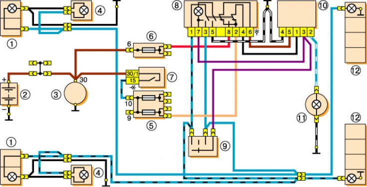
1 – front lights with direction indicator lamps; 2 – battery; 3 – generator; 4 – side direction indicators; 5 – main fuse box; 6 – additional fuse box; 7 – ignition switch; 8 – hazard warning switch; 9 – direction indicator switch; 10 – Direction indicators and hazard warning lights relay; 11 – speedometer with direction indicator indicator; 12 – rear lights with direction indicator lamps.
Direction indicators (left and right) are switched on by the steering column switch. Hazard warning mode (all direction indicators are flashing) is switched on by a special switch, which is installed in the radio panel. The emergency signaling relay is fixed on the front panel behind the instrument panel and should ensure that the turn signal lamps flash at a frequency of 90±30 cycles per minute at an ambient temperature of -20 to 50°C and a voltage of 10.8 to 15 V. If one of the turn signal lamps burns out, the flashing frequency of the indicator and the remaining lamps doubles.