
English Русский
Български
Беларускі
Український
Српски
Hrvatski
Română
Polski
Slovenský
Magyar
| Articles | Contacts | Sitemap |   
Repair and maintenance Lada Repair and maintenance Mazda Repair and maintenance Mitsubishi Repair and maintenance Toyota Repair and maintenance Land Rover Repair and maintenance Hyundai Repair and maintenance Nissan
VAZbook.ru


Main     1111   2101   2105   2106   2107   2109   2110   2115   2121  
VAZ-2107 (1982-2012)
  • Main
  • «Zhiguli»
  • VAZ-2107
  • Electrical equipment
  • Engine electrics
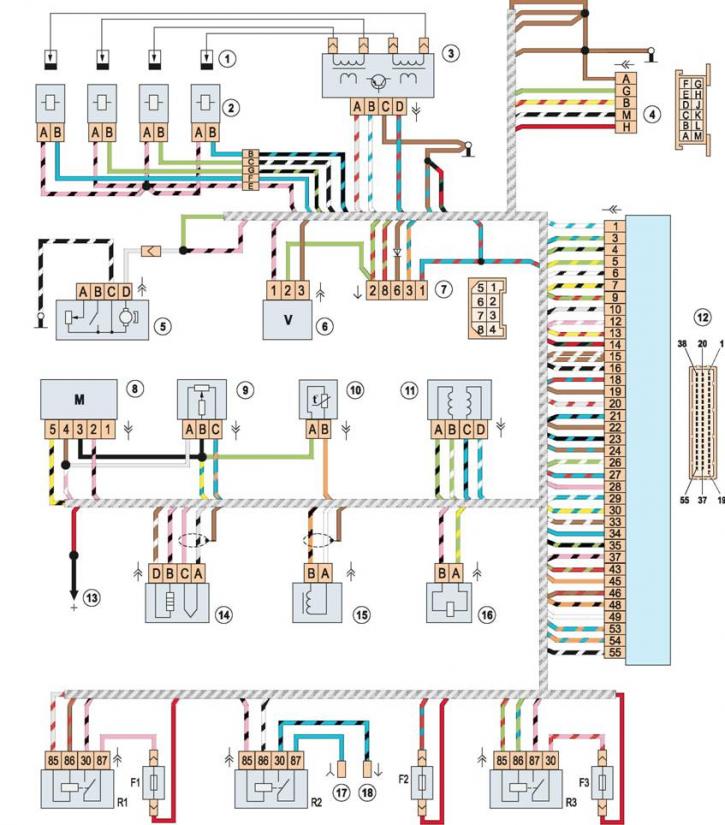
  • Electrical diagram of the engine management system with the M1.5.4N controller

Electrical diagram of the engine management system with the M1.5.4N controller (VAZ-2107)

            0

Electrical diagram of the engine management system with controller M 1.5.4N: 1 - spark plugs; 2 -…

Electrical diagram of the engine management system with controller M 1.5.4N: 1 - spark plugs; 2 - injectors; 3 - ignition module; 4 - diagnostic connector block; 5 - electric fuel pump with fuel level sensor; 6 - vehicle speed sensor; 7 - connection block with instrument panel wiring harness; 8 - mass air flow sensor; 9 - Throttle control sensor; 10 - coolant temperature sensor; 11 - idle speed control; 12 - Electronic control unit (ECU); 13 - to the positive terminal of the battery; 14 - oxygen concentration sensor; 15 - crankshaft position sensor; 16 - Evaporative Evaporative Blow-Off Solenoid Valve; 17 - wire connector to the mounting block (pin 6 of the Sh6 pad); 18 - block of wire to the "+" terminal of the electric fan; R1 - main relay; R2 - electric fan relay; R3 - electric fuel pump relay; F1 - main relay circuit fuse (15A); F2 - ECU fuse (15A); F3 - Electric fuel pump circuit fuse (15A)


The article is copied from the website [vazbook]


This article is available at russian, bulgarian, belarusian, ukrainian, serbian, croatian, romanian, polish, slovak, hungarian
The text was reviewed by the specialist: Grigory Vologodtsev

Share with friends:

Previous articles
VAZ-2107: Engine electrics
Next articles

Ignition distributor — disassembly
Ignition distributor — removal and installation
Ignition timing — checking and adjustment
Closed state angle of breaker contacts — checking and adjustment
Ignition distributor — lubrication
Electrical diagram of the engine control system with the controller January-5.1.3
Generator — removal and installation

More articles from other manuals on VAZ cars:
➠ Electrical diagram of the engine management system with the… VAZ-2104 (1984-2012)
➠ Wiring diagram of the engine management system VAZ-21214 with… VAZ-21214 (1994-2006)
➠ Engine management system — device and diagram VAZ-2110 (1995-2007)
➠ Engine Management System Diagram VAZ-2114 (2004-2013)
➠ Car electrical system diagram VAZ-1111 (1988-1996)
Link in different formats to this page


Visitor comments

No comments yet


How much will 49 + 20 ?


VAZ-2107 (1982-2012) 
  • General information
  • User manual
  • Maintenance
  • Operation and maintenance
  • Power unit
  • Engine repair
  • Fuel system (carburetor)
  • Fuel system (injector)
  • Control system
  • Cooling system
  • Exhaust system
  • Transmission
  • Clutch
  • Car gearbox
  • Cardan gear
  • Rear axle
  • Chassis
  • Front suspension
  • Rear suspension
  • Wheels and tires
  • Steering
  • Brake system
  • Body
  • Exterior
  • Interior
  • Doors and glass
  • Electrical equipment
  • Equipment and devices
  • Headlights and lighting
  • Engine electrics


VAZbook.ru © 2017 · Mobile version · Contact with administration · Sitemap: EN BG BY UA RS HR RO PL SK HU · Site search · News and articles VAZ-1111 · VAZ-11113 · VAZ-2101 · VAZ-21011 · VAZ-2104 · VAZ-2105 · VAZ-21051 · VAZ-2106 · VAZ-21061 · VAZ-2107 · VAZ-21099 · VAZ-2109 · VAZ-2108 · VAZ-2110 · VAZ-2112 · VAZ-2114 · VAZ-2115 · VAZ-2121 · VAZ-21213 · VAZ-21214 ·
The site stores technical data using cookies to improve the service.