
Engine management systems 2112 (l,5i) and 21124 (l,6i) - electronic, with distributed phased fuel injection (i.e. fuel is injected into the intake manifold of each cylinder according to the engine duty cycle). The engine management system consists of the following elements:
- ECU (electronic control unit);
- sensors:
- 1. DPKV (crankshaft position sensor);
- 2. DPRV (camshaft position sensor);
- 3. TPS (throttle position sensor);
- 4. DD (knock sensor);
- 5. DTOZH (coolant temperature sensor);
- 6. DMRV (mass air flow sensor);
- 7. Vehicle speed sensor;
- 8. Oxygen concentration sensor (or two sensors for EURO III);
- 9. Rough road sensor (for EURO III);
- executive devices:
- 1. Main relay;
- 2. Fuel pump relay;
- 3. Nozzles;
- 4. Ignition coils on the engine 21124 (1,6i) or ignition module on engine 2112 (1,5i);
- 5. IAC (idle speed controller);
- 6. The relay of the electric fan of the cooling system;
- 7. Engine malfunction warning lamp;
- 8. Adsorber purge valve;
- connecting wires;
- diagnostic socket.
The engine management system is also integrated:
- car anti-theft system;
- speedometer;
- tachometer.
The main control element of the engine management system is electronic control unit (ECU), or as it is often called - a controller with an integrated microprocessor. In fact, an ECU is a specialized mini-computer in which only one program is installed - engine control, and sensors and actuators form the peripheral equipment of this computer. The ECU receives and analyzes the sensor signals. Based on the received data, the ECU calculates control commands and issues them to the actuators. The ECU has three types of memory*: ROM (ROM), random access memory (RAM) and flash memory (PROM).
ROM - non-volatile memory (that is, the information in the memory is retained when the power is turned off), and is a microcircuit («chip») *. The microcircuit is installed on the computer board through a plug-in connection - a special connector, and is not soldered like other elements. This was done in order to unify the ECU for various car models. The ROM stores the calculation program and the data necessary for the calculation (engine parameters, transmission ratios and other characteristics). This information is individual for each vehicle modification.
Warning. Unqualified ROM reprogramming or chip replacement from another car model (so-called chip tuning) can lead to malfunctions of the engine, failure of the elements of the engine control system, engine damage.
Changes may be made to the design of the ECU by the manufacturer.
During operation, the ECU monitors the health of all elements and circuits of the engine management system. Having detected a malfunction, the ECU puts the engine management system into standby mode and turns on the engine malfunction indicator lamp on the instrument panel. The engine will then be able to continue running (except in the case of a malfunction of the crankshaft position sensor, see below), which allows you to get to the place of repair on your own. The ECU writes the codes of the detected faults to the RAM. It also stores operational information that the ECU microprocessor uses in calculations. When the battery is disconnected from the vehicle's on-board network, all information stored in RAM will be deleted.
The EEPROM stores codes for the car's anti-theft system (immobilizer). This type of memory is non-volatile. After activating the immobilizer, the ECU blocks the operation of the engine management system when trying to start the engine without special electronic keys.
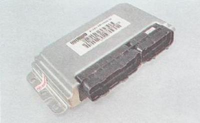
Electronic control unit (ECU)
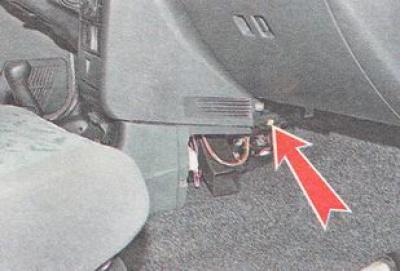
The ECU, immobilizer control unit, fuses and relays of the engine management system are located under the instrument panel console.
Note. The right overlay of the console of the panel of devices is removed.
crankshaft position sensor (DPKV) is designed to generate signals by which the ECU synchronizes its work with the cycles of the engine's working process. Therefore, often this sensor is called a synchronization sensor. The operation of the sensor is based on the principle of induction - when the teeth of the crankshaft pulley pass by the sensor core, alternating current voltage pulses occur in the sensor circuit. The frequency of appearance of pulses corresponds to the frequency of rotation of the crankshaft. The teeth are located around the circumference of the pulley (after 6°). Two of them are separated from each other at an angular distance of 18°. This was done to form reference signals in the sensor circuit - peculiar reporting points, relative to which the ECU determines the position of the crankshaft - top dead centers in the first / fourth and second / third cylinders. Engine operation with a faulty crankshaft position sensor is not possible. The crankshaft position sensor cannot be repaired - in the event of a malfunction, the DPKV is replaced as an assembly.
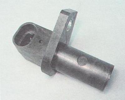
crankshaft position sensor (DPKV)
Camshaft position sensor (DPRV) designed to generate a signal by which the ECU determines the top dead center (TDC) piston of the first cylinder during the compression stroke. Sometimes this sensor is called a phase sensor. The principle of operation of the sensor is based on the Hall effect.
When the protrusion of the ring attached to the intake camshaft pulley passes through the slot in the end of the sensor, the sensor sends an electrical signal to the computer. In the event of a malfunction of the DPRV, the electronic control unit switches the system to a standby mode of operation.
The camshaft position sensor is an electronic device that cannot be repaired. In the event of a malfunction of the DPRV sensor, it should be replaced.
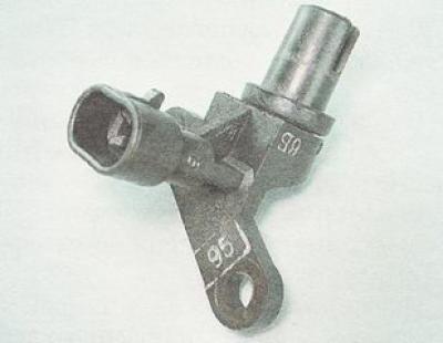
DPRV (camshaft position sensor)
Camshaft position sensor (DPRV) installed in the rear timing belt guard
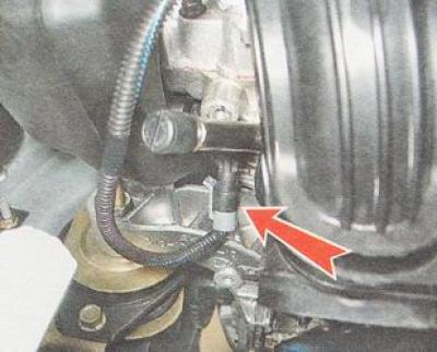
Knock sensor (DD) - piezoelectric, responds to engine vibration. Based on the signals from the sensor, the ECU determines the moment of detonation when the engine is running and, in accordance with this, corrects the ignition timing. In the event of a malfunction of the DD, the electronic control unit switches the system to a backup mode of operation.
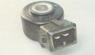
Knock sensor (DD)
Knock sensor (DD) mounted on the front wall of the cylinder block on the vehicle
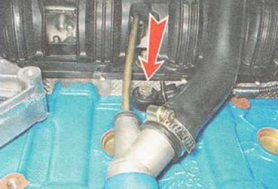
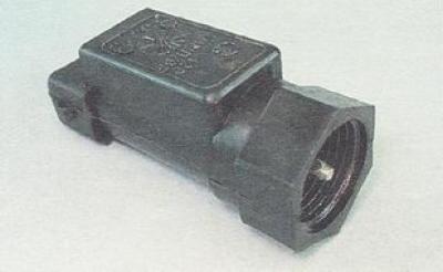
Mass air flow sensor (DMRV) film type, installed between the air filter and the throttle valve. Based on the signal from the sensor, the ECU calculates the amount of air entering the engine cylinders. In the event of a malfunction of the DMRV, the electronic control unit switches the system to a standby mode of operation.
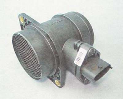
Mass air flow sensor (DMRV)
Throttle position sensor (TPS) mounted on the throttle body, and connected to the throttle shaft. TPS is a variable resistor whose resistance depends on the angle of the throttle valve. Based on the TPS signal, the electronic control unit determines the amount of throttle opening. In the event of a malfunction of the TPS, the electronic control unit switches the system to a backup mode of operation.
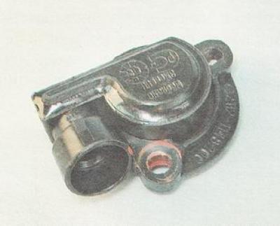
Throttle position sensor (TPS)
idle speed controller (IAC) is a shut-off valve driven by a stepper motor. The IAC is mounted on the throttle body. The ECU, by supplying a controlled signal to the IAC, regulates the engine speed at idle, when starting and warming up the engine.
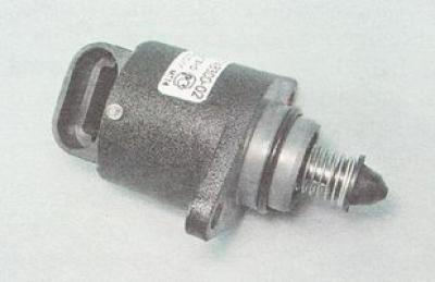
idle speed controller (IAC)
Oxygen concentration sensor provides an output signal from which the ECU determines the oxygen concentration in the exhaust gases. Based on the data received, the ECU adjusts the amount of fuel injected into the engine cylinders, thereby maintaining the optimal proportion of the air-fuel mixture (this is necessary for the efficient operation of the catalytic converter). The sensitive element of the oxygen concentration sensor is located in the exhaust gas stream (before the catalytic converter). The operability of the sensor is possible only when its sensitive element is heated to a temperature not lower than 300°C. To reduce the warm-up time, a heating element is built into the sensor. On the engine 2112 (l,5i) the sensor is installed at the bottom of the intake pipe, and on the engine 21124 (1,6i) - at the top of the catalytic manifold. The location of the oxygen concentration sensor on the manifold allows you to reduce the time it takes for the sensor to warm up to operating temperature.
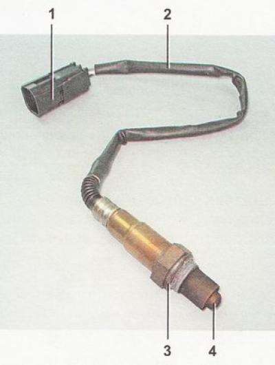
Oxygen concentration sensor: 1 - connecting block; 2 - wiring harness; 3 - sealing ring; 4 - sensing element with holes for supplying exhaust gases
On VAZ 2110, VAZ 2111, VAZ 2112 vehicles that meet the requirements of EURO III toxicity standards, a second oxygen concentration sensor is built into the exhaust gas system after the converter.
Warning. The presence of lead and silicon compounds in the exhaust gases can lead to failure of the oxygen concentration sensor. Therefore, the use of leaded gasoline is not allowed. When repairing the engine, do not use a sealant with a high content of silicone (silicon compounds), whose vapors can get through the crankcase ventilation system into the cylinders and further into the exhaust tract. Use a sealant that specifically states on the packaging that it is safe for the oxygen sensor.
coolant temperature sensor (DTOZH) - a semiconductor device - a thermistor, the electrical resistance of which changes with a change in ambient temperature. The sensor is installed in the thermostat housing. Based on the resistance of the sensor, the ECU evaluates the temperature regime of the engine. The obtained data are used in the calculation of most control commands for the elements of the engine control system, as well as for turning on the electric fan of the engine cooling system. In the event of a malfunction of the DTOZH, the electronic control unit switches the system to a backup mode of operation.
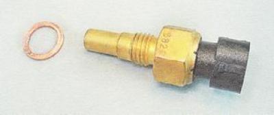
coolant temperature sensor (DTOZH) with copper sealing ring
Vehicle speed sensor installed on the gearbox. The principle of operation of the speed sensor is based on the Hall effect. Based on the pulses generated by the sensor, the ECU calculates the speed of the car. The signal from the speed sensor is also sent to the speedometer.
Vehicle speed sensor
Ignition systems for VAZ 2112 engines (l,5i) and VAZ 21124 (l,6i) have significant design differences: on the VAZ 2112 engine (1,5i) an ignition module is installed, which consists of two two-pin ignition coils made in a single housing. Sparking occurs in two cylinders at the same time (1-4 and 2-3). The ignition module is connected to the spark plugs by high-voltage wires with non-removable tips.
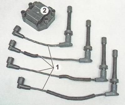
Elements of the ignition system of the injection engine VAZ 2112 (l,5i): 1 - a set of high-voltage wires; 2 - ignition module
On the VAZ 21124 engine (1,6i) four ignition coils are used. They are mounted directly on the spark plugs. This eliminates the reduction in spark power due to current leakage (this is possible if the insulation of high-voltage wires is damaged).
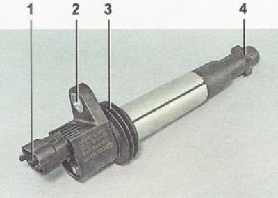
Engine ignition coil VAZ 21124 (l,6i): 1 - pins for connecting wire harness connectors; 2 - eye for attaching the coil; 3 - rubber sealing ring; 4 - tip for connecting to a spark plug
On engines on a VAZ 2110, VAZ 2111, VAZ 2112 car, AU17DVRM spark plugs are used, where:
- A - thread M 14x1.25;
- U - hexagonal part of the body on a 16 mm turnkey basis;
- 17 - glow number;
- D - length of the threaded part 19 mm, with a flat seating surface;
- B - protrusion of the thermal cone of the insulator beyond the end face of the threaded part of the housing;
- R - built-in resistor;
- M - bimetallic central electrode
On the engine, you can install candles of various manufacturers of the same type.
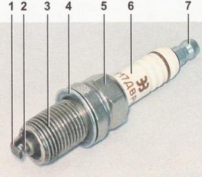
Spark plug: 1 - side electrode; 2 - central electrode (in the thermal cone of the insulator); 3 - threaded part of the body; 4 - sealing ring; 5 - hexagonal part of the turnkey housing; 6 - insulator (It has a spark plug label on it); 7 - contact tip (removable, threaded)
Nozzle - This is an electromagnetic needle valve, on the outlet pipe of which a sprayer with four calibrated holes is made. The injector opens on a signal from the ECU, while pressurized fuel is injected directly onto the intake valve. The amount of fuel entering the cylinder is controlled by the opening time of the injector. The engine has one injector for each cylinder.
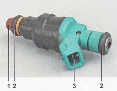
Engine nozzle VAZ 2112 (l,5i): 1 - atomizer; 2 - sealing rubber ring; 3 - terminals for connecting the wiring harness
Canister purge valve installed on the cover of the adsorber housing (see more details. "Engine power system - device, description, diagram").
Diagnostic connector designed to connect an external diagnostic device (for example, DST-2M) to the engine management system. The diagnostic connector is installed on the instrument panel from below on the driver's side.
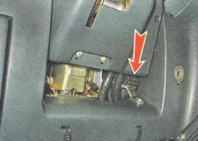
Location of the diagnostic connector.
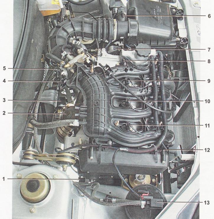
Location of elements of the injection engine control system VAZ 21124 (l,6i) in the engine compartment*: 1 - crankshaft position sensor (DPKV); 2 - oxygen concentration sensor (DCC); 3 - vehicle speed sensor; 4 - idle speed regulator (IAC); 5 - throttle position sensor (TPS); 6 - mass air flow sensor (DMRV); 7 - installation location of the DTOZH coolant temperature sensor (on the thermostat housing); 8 - ignition coil of the fourth cylinder; 9 - ignition coil of the third cylinder; 10 - ignition coil of the second cylinder; 11 - ignition coil of the first cylinder; 12 - installation location of the camshaft position sensor (DPRV); 13 - adsorber purge valve
* The engine trim has been removed.
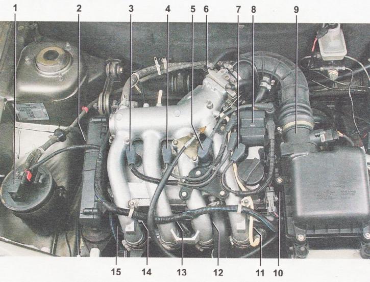
Location of elements of the VAZ 2112 injection engine control system (l,5i) in the engine compartment*: 1 - adsorber purge valve; 2 - installation location of the crankshaft position sensor (DPKV) in the tide of the cylinder block; 3, 4, 5 and 7 - high-voltage spark plug wires of the first, second, third and fourth cylinders, respectively; 6 - throttle position sensor (TPS) and idle control (IAC) (mounted on throttle body); 8 - ignition module; 9 - mass air flow sensor (DMRV); 10 - installation location of the coolant temperature sensor (DTOZH) (under the air filter on the thermostat housing); 11, 12, 13 and 14 - nozzles of the fourth, third, second and first cylinders, respectively; 15 - installation location of the camshaft position sensor (DPRV)
* The engine trim has been removed.
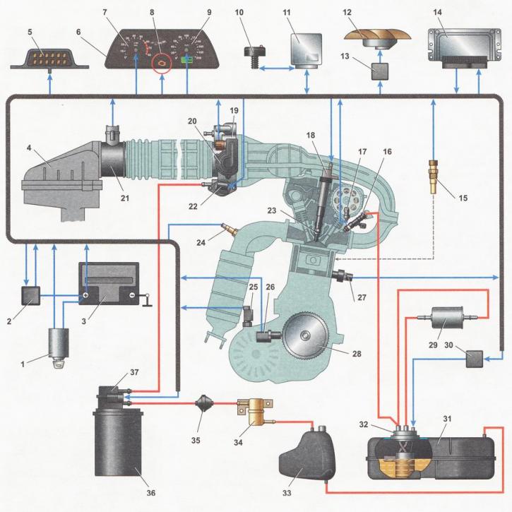
Scheme of the injection engine control system *: 1 - ignition lock; 2 - main relay; 3 - battery; 4 - air filter; 5 - diagnostic connector; 6 - instrument panel; 7 - tachometer; 8 - control lamp for a malfunction of the engine management system; 9 - speedometer; 10 - immobilizer sensor with indicator; 11 - immobilizer control unit; 12 - electric fan of the engine cooling system; 13 - electric fan relay; 14 - electronic control unit (ECU); 15 - coolant temperature sensor; 16 - nozzles; 17 - camshaft position sensor (phase sensor); 18 - ignition coil *; 19 - throttle assembly; 20 - throttle position sensor (TPS); 21 - mass air flow sensor (DMRV); 22 - idle speed controller (IAC); 23 - spark plug; 24 - oxygen concentration sensor*; 25 - vehicle speed sensor; 26 - crankshaft position sensor (DPKV); 27 - knock sensor (DD); 28 - crankshaft pulley; 29 - fuel filter; 30 - fuel pump relay; 31 - fuel tank; 32 - fuel module; 33 - separator; 34 - gravity valve; 35 - check valve; 36 - adsorber; 37 - adsorber purge valve
* The diagram is shown on the example of a car with an injection engine VAZ 21124 (l,6i). By car with a VAZ 2112 engine (l,5i) instead of four coils, an ignition module is installed; the oxygen concentration sensor is installed in the intake pipe.