




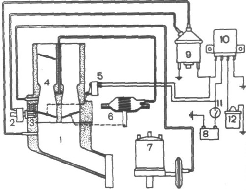
Fig. 34. Diagram of the exhaust gas toxicity reduction system:
1 - inlet pipe; 2 - forced idle economizer; 3 - autonomous idle system; 4 - carburetor; 5 - micro switch; 6 - pneumatic drive of the secondary chamber throttle valve; 7 - ignition distributor with vacuum corrector; 8 - battery; 9 - electro-pneumatic valve; 10 - electronic control unit; 11 - ignition switch; 12 - ignition coil.
The original source is located on the website: VAZBOOK