




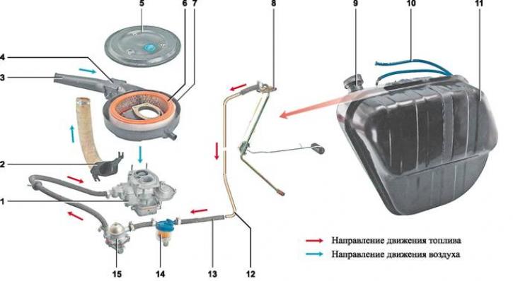
Details of the fuel system of a carburetor engine: 1 - carburetor; 2 - warm air intake; 3 - cold air intake; 4 - thermostat; 5 - air filter housing cover; 6 - filter element; 7 - air filter housing; 8 - fuel level and reserve indicator sensor; 9 - filler neck; 10 - ventilation hose; 11 - fuel tank; 12 - fuel line; 13 - fuel hose; 14 - fuel filter; 15 - fuel pump
Fuel tank welded from two halves stamped from sheet leaded steel. The outside of the tank is painted with black enamel.
The car has a 39-liter fuel tank. The tank is located in the trunk on the right side in the direction of travel and is attached to the body with a clamp tightened with a bolt. The filler neck is brought out into a niche on the right rear wing and is closed with a threaded plug. For ventilation, the fuel tank has a hose that is brought out into the filler neck niche. On top of the tank, through a sealing gasket, is installed fuel level and reserve indicator sensor. The sensor sends data on the remaining fuel in the tank to the instrument panel. When there is 4.0-6.5 liters of fuel left, a control lamp lights up on the instrument panel.
Fuel lines are made of galvanized steel tubes and are secured to the bottom of the body with holders. The fuel system components are connected to each other with rubber hoses secured with clamps.
Fuel pump - diaphragm type, with mechanical drive and manual pumping lever. The pump is located on the left side of the cylinder block and is secured through a heat-insulating spacer and gaskets on two studs with nuts. The pump is driven through a pusher from an eccentric on the auxiliary drive shaft or from a manual pumping lever. The pump capacity is at least 60 l/h at a pumping frequency of 2000 cycles per minute. The pressure created by the pump is within 0.20- 0.30 kgf/cm². The pump consists of a lower casing with drive levers, an upper casing with inlet and discharge valves, a diaphragm unit and a cover. The diaphragm unit has two upper working and one lower (safety) diaphragms mounted on the rod. Between the working and safety gaskets, internal and external spacer gaskets are installed. In order to prevent fuel from entering the engine crankcase in the event of damage to the working diaphragms of the fuel pump, a hole is made in the external gasket for draining fuel.
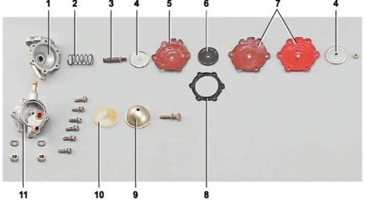
Fuel pump parts: 1 - lower body; 2 - return spring; 3 - rod; 4 - diaphragm assembly plate; 5 - safety diaphragm; 6 - internal spacer gasket; 7 - working diaphragms; 8 - external spacer gasket; 9 - pump cover; 10 - mesh filter; 11 - upper body
Air filter - dry, with a replaceable filter element that cleans the air entering the carburetor. The filter housing is installed on the carburetor cover through a rubber gasket with spacer bushings on four studs and is secured with self-locking nuts. The filter housing is closed from above with a cover with a rubber sealing gasket. In the air duct in front of the air filter housing, a thermostat, which allows changing the temperature of the incoming air. Depending on one of the three positions of the thermostat flap, air is taken in through the warm or cold air intake, or from both simultaneously. The flap position is set manually in accordance with the ambient air temperature. The air filter housing is connected by a crankcase gas supply hose to the oil separator cover of the crankcase ventilation exhaust system. A flame arrester is installed in the crankcase gas supply hose.
The car is equipped with a carburetor model 2107-1107010.
Carburetor emulsion type, two-chamber, with a falling flow. The combustible mixture is formed from the air entering through the air filter and the fuel supplied by the pump. This ensures an uninterrupted supply of the combustible mixture of the optimal composition in all engine operating modes. The prepared mixture is sucked through the intake manifold into the engine cylinders. The carburetor consists of three body parts: the cover, the carburetor body and the throttle body.
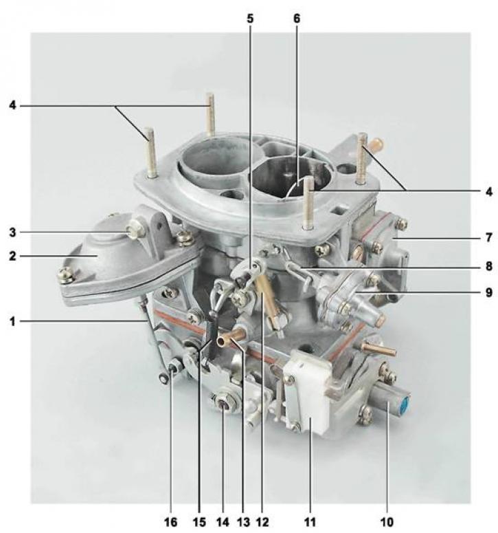
Carburetor 2107-1107010: 1 - secondary chamber throttle valve pneumatic drive rod; 2 - pneumatic drive of the secondary chamber throttle valve; 3 - bolt for fastening the air damper drive rod casing; 4 - air filter housing mounting stud; 5 - coupling with screw for fastening the air damper drive rod; 6 - air damper; 7 - accelerator pump cover; 8 - diaphragm rod of the starting device; 9 - starting device; 10 - forced idle economizer; 11 - micro switch; 12 - telescopic rod; 13 - crankcase gas outlet pipe; 14 - primary chamber throttle valve axis; 15 - return spring for locking the opening of the secondary chamber flap; 16 - secondary chamber throttle valve axis
The carburetor is mounted on four studs of the intake manifold. The carburetor cover contains the inlet necks of the primary and secondary mixing chambers, the fuel supply nipple from the fuel pump, and the fuel and air channels. The cover also contains a fuel supply needle valve and a float, which provide the required fuel level in the float chamber. The carburetor body contains large diffusers and a float chamber.
The original source is published on the website VAZBOOK
Inside the large diffusers are installed removable small diffusers, cast together with the economizer sprayers and main dosing systems. In the carburetor body are made air and fuel channels, installed air and fuel jets and accelerator pump sprayer.
The accelerator pump supplies an additional portion of fuel to the primary mixing chamber when the accelerator pedal is pressed sharply. The diaphragm-type pump is made in the lug of the housing and is closed with a cover secured with four screws. The pump diaphragm is moved by a lever. To ensure smooth running and, accordingly, smooth and prolonged injection, a damping spring is installed in the telescopic cup of the diaphragm. The accelerator pump lever is driven from a cam secured to the axis of the primary chamber throttle valve.
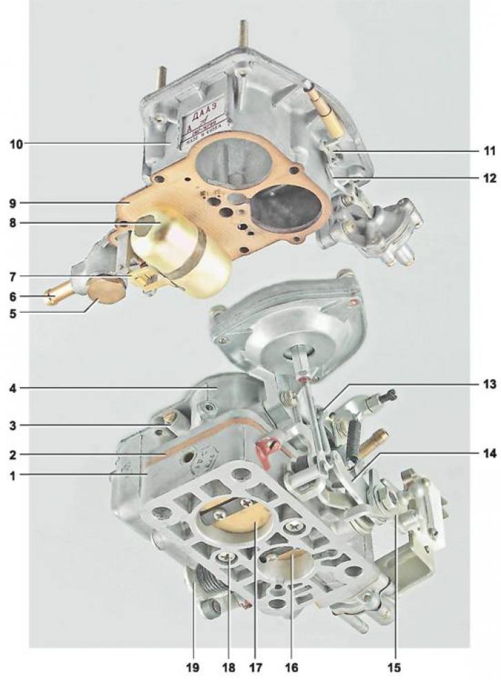
Carburetor cover and body: 1 - throttle body; 2 - heat-insulating spacer; 3 - secondary chamber transition system fuel jet housing; 4 - carburetor body; 5 - carburetor fuel filter plug; 6 - fuel nipple; 7 - needle valve body; 8 - float; 9 - gasket; 10 - carburetor cover; 11 - air damper lever; 12 - a rod connecting the air damper lever with the diaphragm rod of the starting device; 13 - throttle valve connection rod with starting device drive; 14 - lever limiting the opening of the secondary chamber throttle valve; 15 - throttle valve drive lever; 16 - primary chamber throttle valve; 17 - secondary chamber throttle valve; 18 - throttle body mounting screw; 19 - accelerator pump drive cam
The throttle valve housing is attached to the carburetor body from below with two screws. Rotary throttle valves are mounted on axles in the primary and secondary mixing chambers. The primary chamber throttle valve is driven mechanically through a system of adjustable rods from the gas pedal. The secondary chamber throttle valve is driven pneumatically. The drive housing, with a diaphragm and a return spring, is secured to the carburetor body with two screws. The drive rod is pivotally connected to the lever on the secondary chamber throttle valve axle. The pneumatic drive begins to open it when the primary chamber throttle valve is deflected by an angle greater than 48° and a vacuum is created in the mixing chambers sufficient to open the valve.
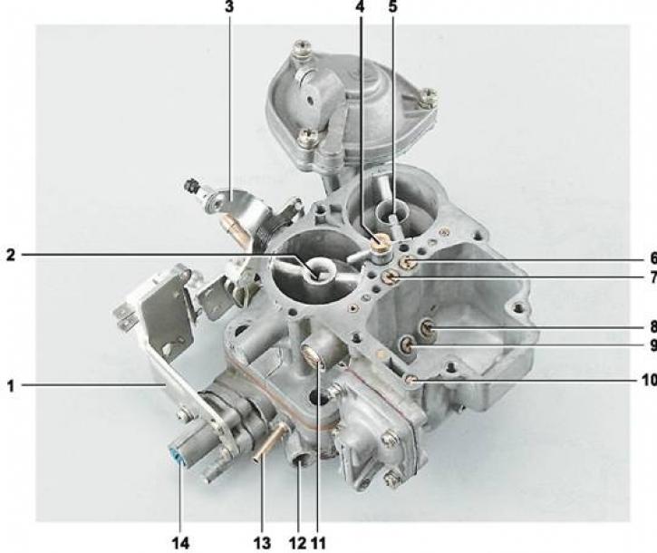
Carburetor body: 1 - microswitch bracket; 2 - small diffuser of the primary chamber; 3 - three-arm lever; 4 - accelerator pump sprayer; 5 - small diffuser of the secondary chamber; 6 - secondary chamber main air jet; 7 - main air jet of the primary chamber; 8 - secondary chamber main fuel jet; 9 - main fuel jet of the primary chamber; 10 - adjusting screw for fuel supply by accelerator pump; 11 - idle system fuel jet housing; 12 - adjusting screw for idle mixture composition (quality); 13 - nipple for supplying vacuum to the vacuum regulator of the ignition distributor; 14 - idle mixture quantity adjusting screw with limiting sleeve
To start and operate the engine during warm-up, the carburetor has a starting device and an air damper. The air damper is mounted on an axis in the inlet neck of the primary chamber of the carburetor cover. The damper is driven from the driver's seat by a cable from the control handle. The body of the starting device is attached to the carburetor cover with two screws. The diaphragm rod of the starting device drive is connected by a rod to the air damper lever. The cavity of the starting device is connected by an air channel to the primary mixing chamber. When the engine is started, a vacuum is created in the cavity. The diaphragm rod presses the return spring, acts on the rod and slightly opens the air damper.
Idle speed adjustment is performed by the mixture composition (quality) and quantity screws. The composition adjustment screw is installed in the hole of the throttle body lug and is closed with a plug. The mixture quantity adjustment screw is installed in the economizer cover.