




Contents: Examination ↓ Starter repair 4216.3708-02 ↓ Starter assembly 4216.3708-02 ↓ Starter repair 5722.3708 ↓ Starter assembly 5722.3708 ↓
Examination
To perform the work you will need a multimeter.
1. Remove the starter (see "Starter - removal and installation").
2. Clean the outer surface of the starter from dirt.
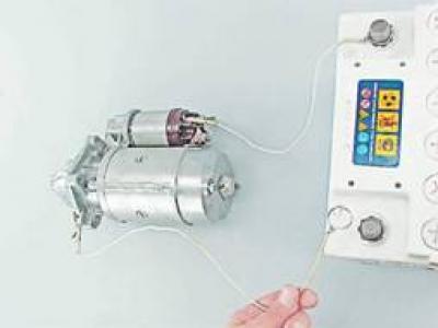
3. To check the traction relay, connect its output "50" with the positive terminal of the battery, and the starter housing with the negative one. In this case, the anchor of a working relay pushes the drive gear into the window of the front cover with a characteristic click.
4. To check the armature and stator windings, remove the rear cover of the starter and disconnect the brush assembly (see below, "Starter repair 4216.3708-02").
5. Having connected one ohmmeter probe to the body, we alternately connect the other to the terminals of the stator windings, checking that they are not shorted to the body.
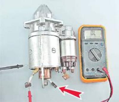
If there is no short circuit, the ohmmeter should show a resistance of at least 10 kOhm.
6. Having connected the ohmmeter probes to the terminals of the stator windings, we check them for breakage.
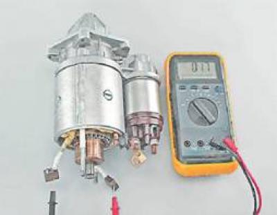
If the resistance tends to infinity, the winding has broken.
7. Having connected one probe of the ohmmeter to the body, we connect the other one alternately to the contact plates of the armature, checking for the absence of a short circuit of the armature windings to ground.
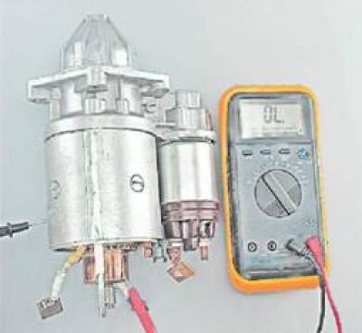
If there is no short circuit, the ohmmeter should show a resistance of at least 10 kOhm.
Starter repair 4216.3708-02
1. Using a 13 mm socket wrench, unscrew the nut and remove the stator winding terminal from the contact bolt.
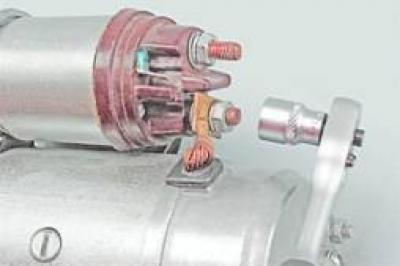
2. Using a slotted screwdriver, unscrew the three screws securing the traction relay.
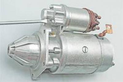
3. Remove the traction relay with the rod and spring.
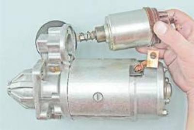
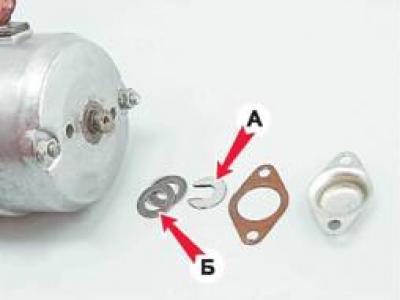
4. Using a slotted screwdriver, unscrew the two screws securing the anchor shaft casing.
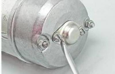
5. Remove the casing with the gasket, the lock washer A of the rotor shaft and the adjusting washers B.
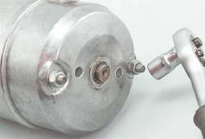
6. Using a 10 mm socket wrench, unscrew the two nuts securing the rear cover of the starter and remove it.
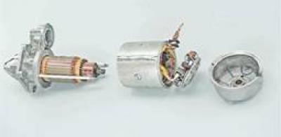
7. Disconnect the front cover from the body together with the tie rods and anchor.
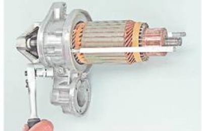
8. Using a 10 mm socket wrench, unscrew the lock nut of the eccentric axis of the drive lever.
9. Using a slotted screwdriver, unscrew the lever axle.
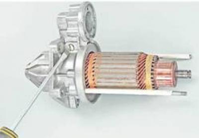
10. Remove the eccentric axle of the starter drive lever.
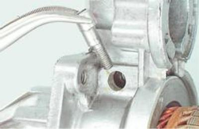
11. Remove the anchor from the tie rods of the body, disengaging the lever fork from engagement with the leash ring.
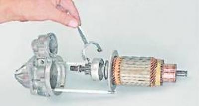
12. Having supported the anchor shaft on a wooden surface, we press the limiting ring from the retaining ring using a suitable mandrel.
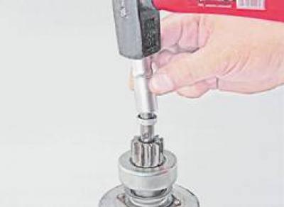
13. Using a slotted screwdriver, remove the retaining ring from the shaft.
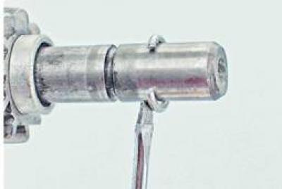
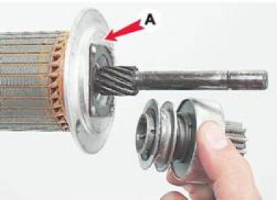
14. Remove the limiting ring, the overrunning clutch with the drive gear and the partition of housing A from the armature shaft.
Starter assembly 4216.3708-02
1. Wash the starter parts with white spirit or kerosene, blow with compressed air. Check the condition of the parts. The covers and housing must be free of cracks. The gear teeth must not have significant wear. The gear must easily rotate relative to the hub only in one direction - in the direction of rotation of the anchor. There must be no burrs, nicks or signs of wear on the surfaces of the splines and journals of the shaft. There must be no burns on the working surface of the collector. Remove small burns with fine-grained sandpaper. The brushes must move freely in the grooves of the brush holders. The brush holders of the "positive" brushes must not have a short circuit with the "ground". Brushes worn to a height of less than 12 mm are replaced with new ones.
2. Lubricate the bearing surfaces and splines of the armature shaft, the splines of the overrunning clutch hub, the bearing bushings in the starter covers and the drive lever axle with engine oil. Lubricate the drive ring of the overrunning clutch hub with plastic grease.
3. We install a partition and an overrunning clutch with a drive gear on the armature shaft.
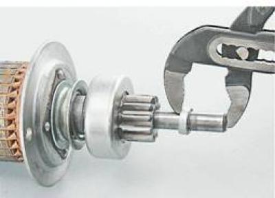
4. Place the gear travel limiting ring on the shaft so that the smaller diameter of the inner conical surface of the ring faces the gear. Install the locking ring in the shaft groove, squeeze it and press the limiting ring onto it with sliding pliers, if necessary pressing the locking ring into the groove with a slotted screwdriver.
5. Next, we assemble the starter in the reverse order.
6. Before installing the armature shaft casing, check the axial play of the armature shaft, which should be no more than 0.5 mm. If necessary, adjust it by installing adjusting washers on the armature shaft (see above "Repair of starter 4216.370802", item 5).
7. Install the casing.
8. Install the eccentric axle of the gear drive lever. Press the lever to check the clutch movement. The lever rollers should not come out of the grooves of the ring. If necessary, adjust the position of the lever by rotating the axle. Use a 10 mm wrench to tighten the nut, holding the axle with a slotted screwdriver from turning.
9. Install and connect the traction relay.
Starter repair 5722.3708
1. Using a 10 mm socket wrench, unscrew the nut securing the wire tip to the terminal (contact bolt) traction relay.
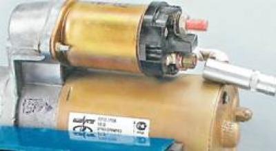
2. Remove the wire tip from the contact bolt of the traction relay.
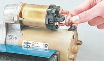
3. Using an 8 mm socket wrench, unscrew the two bolts securing the traction relay.
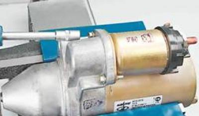
4. Remove the traction relay from the starter (in this case it is necessary to disconnect the relay core earring from the upper end of the drive lever).
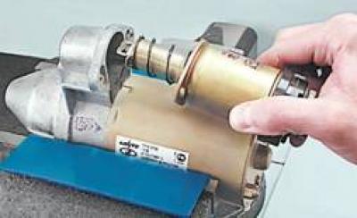
Recommendation. Check the ease of movement of the traction relay core. Connect an ohmmeter to the terminals of the traction relay and, by pressing the anchor to the stop, make sure that the contact bolts close (electrical resistance is close to zero). The faulty traction relay must be replaced.
5. Using a 10 mm socket wrench, unscrew the two nuts of the tie rods.
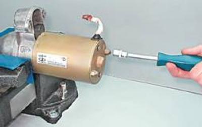
6. Carefully disconnect the stator from the front cover and remove the stator from the studs.
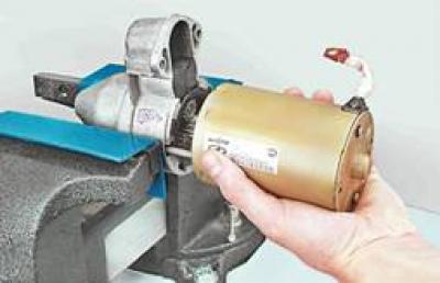
7. Remove the central gear of the planetary gearbox (sometimes the gear remains on the armature shaft).
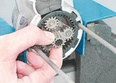
8. Using a slotted screwdriver, remove the three planetary gears of the gearbox one by one.
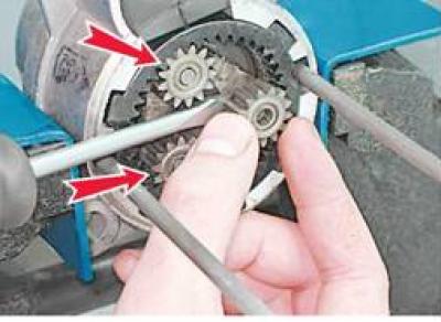
Recommendation. Check the condition of the planetary gearbox. The needle bearings of the satellite gears should not be damaged. There should be no chips, burrs, traces of corrosion or other damage on the gearbox teeth. It is necessary to replace the faulty gearbox elements (either the drive or the starter assembly).
9. Using a screwdriver, press against the top of the front cover of the starter and pry up the drive lever support.
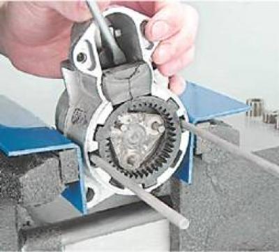
10. Remove the drive from the cover together with the drive shaft, drive lever, lever support and external gear of the gearbox.
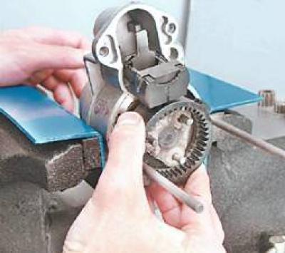
Recommendation. Check the condition of the drive. The drive should move freely along the shaft splines without jamming. The drive gear should be screwed on freely in one direction only, chipped teeth and strong nicks on the lead-in part of the teeth are not allowed. Minor defects can be removed with a diamond file or an abrasive stone. It is necessary to replace a faulty and heavily worn drive (or starter assembly).
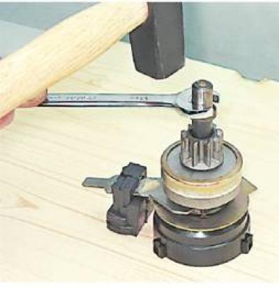
11. Using a hammer and a 13 mm open-end wrench, knock off the starter drive travel limiter ring (in this case, a wooden block or a piece of hard rubber should be placed under the gearbox gear).
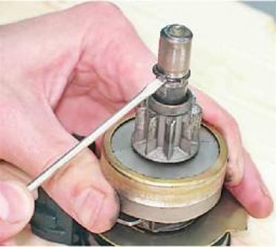
12. Using a slotted screwdriver, remove the drive travel limiter retaining ring from the groove in the shaft and remove the retaining ring and travel limiter ring from the shaft.
13. Remove the drive assembly with the lever and clutch from the shaft.
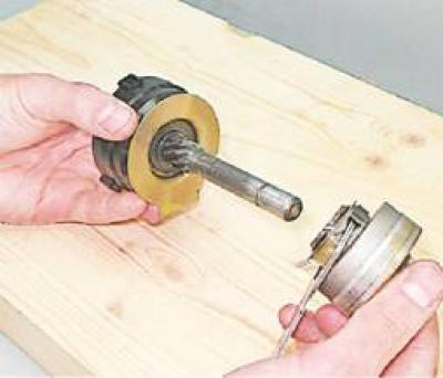
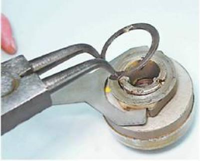
14. Using special expansion pliers, remove the retaining ring of the drive lever coupling.
15. Remove the washer (2) and the coupling (5) together with the drive lever (3) from the drive (4).
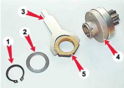
Note: When replacing only the drive, further disassembly of the starter is not necessary.
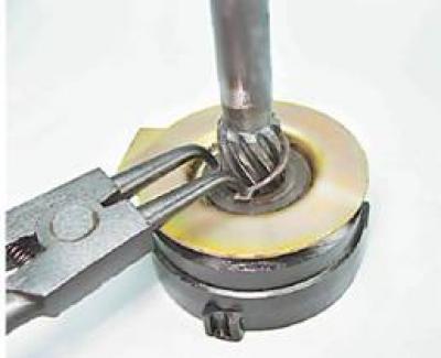
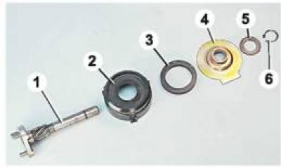
16. Using special expanding pliers, remove the retaining ring (see photo p. 17, pos. 6) drive shaft supports.
17. From the drive shaft (1), sequentially remove the thrust washer (5), shaft support (4), sealing rubber ring (3) and external gear of the planetary gear (2).
18. Using a Phillips screwdriver, unscrew the two screws securing the brush assembly to the rear cover of the starter.
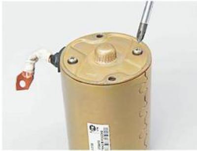
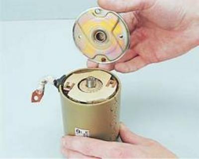
19. Remove the back cover.
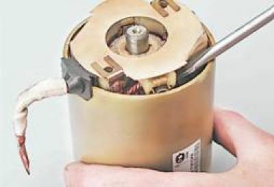
20. Using a slotted screwdriver, remove the brush assembly from the armature collector.
21. Remove the front support of the anchor shaft.
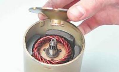
22. Remove the thrust washer from the armature shaft.
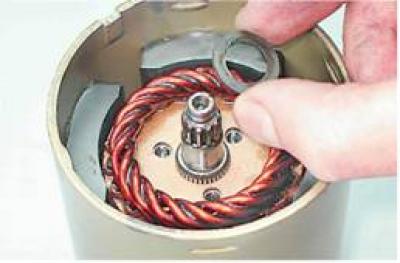
23. Overcoming the force of the magnets, we remove the anchor from the stator.
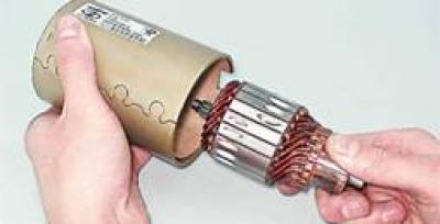
24. Inspect the commutator and armature windings.
Note: Traces of charring of windings are not allowed - such anchor must be replaced.
25. Clean the dirty commutator with fine-grained sandpaper ("zero"), clamping the armature shaft through a strip of thick paper in the chuck of an electric drill. Wash the armature with water and detergent to remove dirt, coal dust and abrasive residues and carefully wipe dry with a clean rag, blow with compressed air from a tire pump.
26. Replace worn brushes (the height from the working edge to the outlet is equal to or less than 3.5 mm) and brushes that have mechanical damage.
27. Wash the gearbox and drive parts with white spirit or kerosene.
Starter assembly 5722.3708
The brush assembly can be installed on the starter armature collector using a special mandrel or tool head of the appropriate size and shape. If they are not available, the brushes can be installed without these devices. To do this:
1. Using two screws, attach the brush assembly to the rear cover of the starter.
2. Lubricate the end of the anchor shaft with two drops of motor oil.
3. Insert four brushes into the corresponding brush holders. Without inserting the brush springs into the brush holders, place the brush assembly on the armature collector.
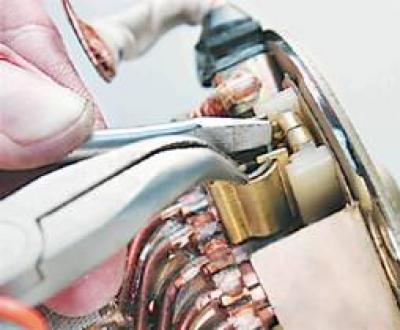
4. Using thin-nosed pliers, bend back the outer spring stops of all four brushes.
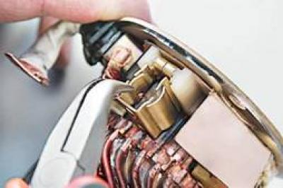
5. Insert the spring into the brush holder.
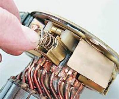
6. Holding the spring with a screwdriver, bend the four spring stops with pliers. Install the remaining three springs in the same way.
7. Insert the starter anchor into the stator with the brush assembly and rear cover placed on it (in this case, it is necessary to hold the anchor so that its collector does not come out of engagement with the brush assembly).
Further assembly of the starter is performed in the reverse order of disassembly. In this case, apply plastic grease to the gearbox parts. Before installing the drive, dip it in engine oil and let the oil drain. The bushings in which the anchor and drive shafts rotate, as well as the screw splines of the drive, are lubricated with engine oil.
8. To ensure that the starter is assembled correctly, before installation, check its functionality, as shown at the beginning of the section.