
Alternator check 372.3701
You will need a multimeter to do the job.
1. Remove the generator from the car (see "Generator - removal and installation").
2. We clean the outer surface of the generator from dirt with a rag.
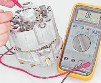
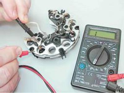
3. By connecting the positive probe of the ohmmeter to the output "30", and the negative probe to the generator housing, check for "breakdown" generator diodes.
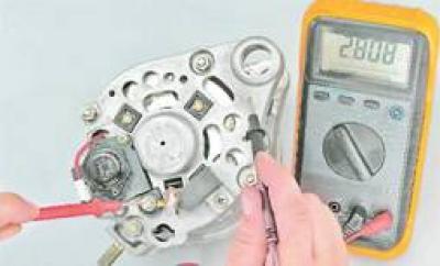
If the ohmmeter shows a resistance close to zero, a breakdown of one or more diodes has occurred or the stator winding has shorted to the housing.
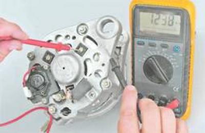
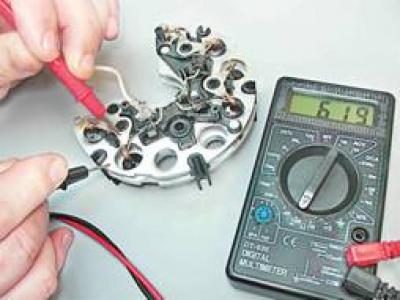
4. By connecting the positive probe of the ohmmeter to the output "30", and the negative one - to one of the bolts of the rectifier unit, we check the positive diodes.
If the ohmmeter shows a resistance close to zero, then a breakdown of one or more diodes has occurred.
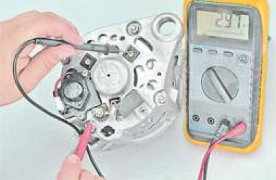
5. By connecting the positive probe of the ohmmeter to one of the rectifier unit mounting bolts, and the negative one to the generator housing, we check for "breakdown" generator negative diodes. If the ohmmeter shows a resistance close to zero, then a breakdown of one or more diodes has occurred.
6. To check the capacitor, remove it from the generator (see below "Repair"). When connecting the ohmmeter probes to the capacitor terminals, the resistance should decrease and then gradually increase.
7. To check the regulator, remove it from the generator (see below "Repair"). When you press the brushes, they should move freely in the grooves, be spring-loaded. The protrusion of the brushes in the free state from the brush holder must be at least 5 mm, otherwise we replace the regulator.
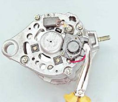
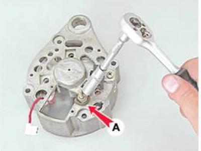
8. Conclusion "IN" voltage regulator is connected to the positive terminal of the battery, and the negative terminal (shown by arrow A) - With "weight". We measure the voltage at the contacts of the brush assembly with a voltmeter.
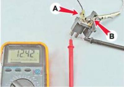
If there is no voltage, then the regulator is faulty.
9. By connecting one contact of the ohmmeter to the housing, and the other to the contact ring of the rotor, we check the absence of a short circuit in the rotor winding to the generator housing.
If the ohmmeter shows a resistance close to zero, then a short circuit has occurred.
A defective rotor, stator, capacitor or voltage regulator must be replaced. If one diode fails, we replace the rectifier assembly.
Generator repair 372.3701
To perform the work, you will need: a two- or three-jaw puller, a mandrel for pressing out the front bearing, a mandrel for pressing in the rear bearing.
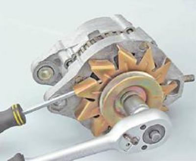
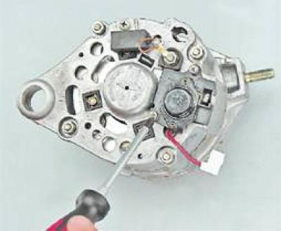
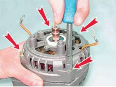
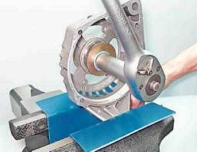
1. Holding the rotor from rotation with a screwdriver, use a 19 mm socket wrench to unscrew the nut securing the pulley and the fan impeller.
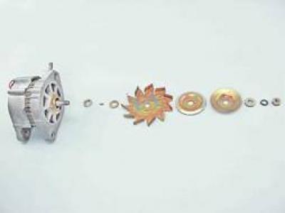
2. Remove the pulley parts, fan impeller, segment key and restrictive washers from the shaft.
3. To remove the voltage regulator, disconnect the wire block from it.
4. Using a Phillips screwdriver, unscrew the two screws securing the voltage regulator.
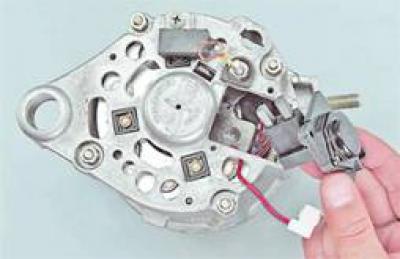
5. We take out the voltage regulator assembly with the brush assembly from the generator housing.
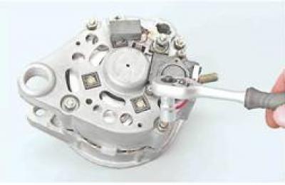
6. Using a 10 mm socket wrench, unscrew the four nuts securing the generator covers and remove the connecting bolts.
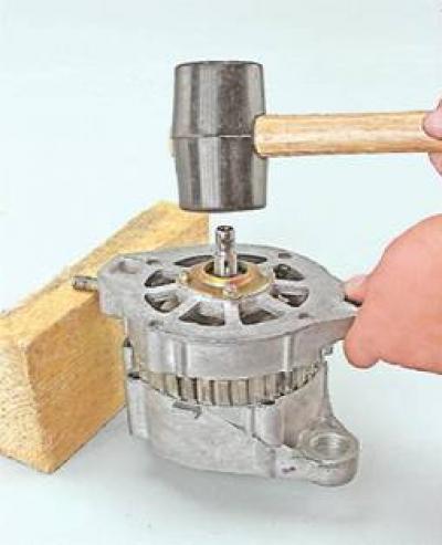
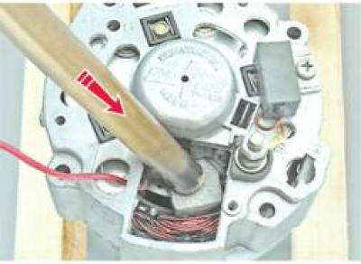
7. Leaning the front cover of the generator on a wooden block, with light blows on the shaft we press it from the stator.
8. Remove the generator cover and spacer.
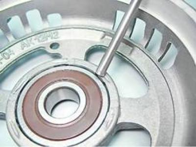
9. Check the technical condition of the front bearing. While holding the cover, we shake and turn in both directions the inner ring of the bearing. The rotation of the bearing must be smooth, the axial play is negligible. We replace the defective bearing.
10. When replacing the front bearing with an 8 mm socket or box wrench, unscrew the four nuts. If the nuts do not turn away, then we grind off the sharpened ends of the bolts.
Attention! After installing the bolts and tightening the nuts, the ends of the bolts must be punched out. If the length of the bolts is not enough for their punching, then we replace the bolts.
11. We take out the bolts and remove the inner and outer washers of the bearing.
12. With a suitable mandrel, we press out the bearing.
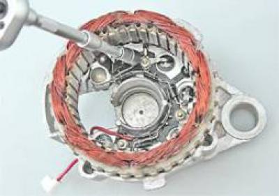
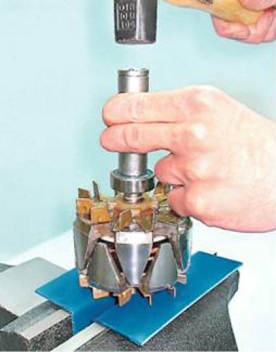
13. Supporting the edges of the back cover of the generator (for example, two wooden blocks), knock out the rotor with a soft metal drift.
14. Check the technical condition of the rear bearing. The rolling of the bearing should be smooth, the axial play should be negligible. When the outer ring rotates quickly, there should be no noise. We replace the defective bearing.
15. If it is necessary to replace the bearing, we press it from the rotor shaft with a puller.
16. Using an 8 mm socket wrench with an extension, unscrew the three nuts securing the rectifier unit and the stator winding leads.
17. After removing the two bolts, remove the stator from the cover.
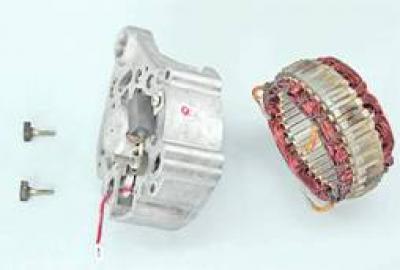
The insulation of the stator winding wires must be free from overheating.
18. Using a 10 mm socket wrench with a deep head, unscrew the output nut "30" and remove the insulating washer A.
19. Remove the rectifier block.
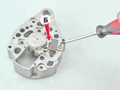
21. Using a Phillips screwdriver, unscrew the screw securing the capacitor and remove it. We remove the third bolt from the hole in the cover (B) rectifier mounting.
Alternator assembly 372.3701
1. We clean the generator parts from dirt and dust, blow with compressed air, metal parts (except bearings) rinse with white spirit or kerosene.
2. With a mandrel that matches in diameter with the inner ring, lightly press the new bearing onto the rotor axis.
3. We check the mounting holes of the bearings in the covers. Holes should not be deformed, their surfaces should be free of burrs. If necessary, with a needle file or a scraper, we restore the chamfer of the edges of the holes. Replace cracked covers.
4. The misalignment of the holes in the ears of the generator covers should be no more than 0.4 mm. When assembling, for the mutual orientation of the covers, we use a mounting bolt and a buffer sleeve.
5. Assembly of the generator is carried out in reverse order.
Generator disassembly 9412.3701
1. Remove the generator from the car (see "Generator - removal and installation").
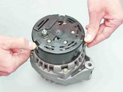
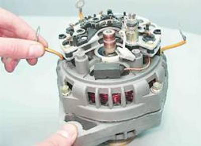
2. Having pressed the three spring clips, remove the protective cover of the rectifier unit.
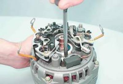
3. Using a Phillips screwdriver, unscrew the two screws securing the voltage regulator.
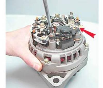
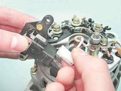
4. Disconnect the wire block from the output of the voltage regulator and remove the regulator.
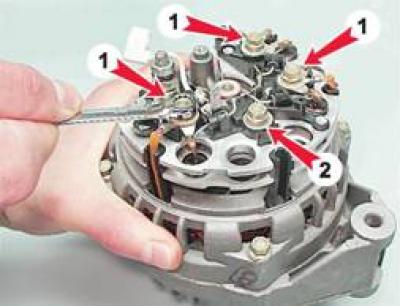
5. With an 8 mm spanner, unscrew the three bolts (1), connecting the terminals of the stator windings with the rectifier unit, and one more bolt (2), fixing the rectifier block (note how the insulating and thrust washers are installed).
6. Carefully bend the wire of the stator winding leads to the side.
7. Using a Phillips screwdriver, unscrew the screw securing the capacitor.
8. Remove the rectifier unit along with the capacitor. Using a 10 mm socket wrench, unscrew the two nuts of the contact bolt. We remove the remote and insulating bushings from the bolt, remove the bolt from the rectifier unit and remove the capacitor tip from the contact bolt.
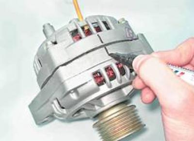
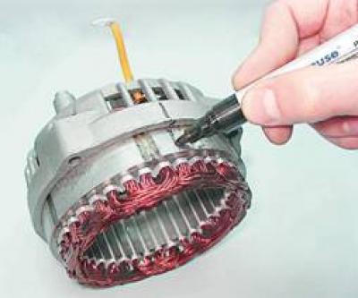
9. Mark with a marker the relative position of the front and rear covers of the generator (to simplify assembly).
10. Using an 8 mm socket wrench, unscrew the four bolts that tighten the front and rear covers of the generator.
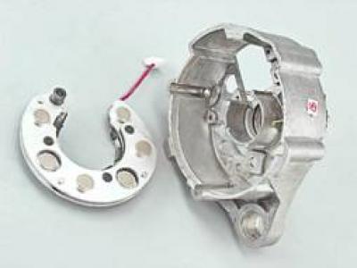
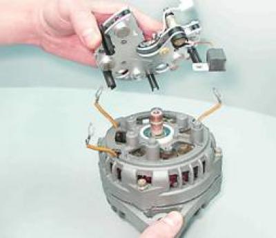
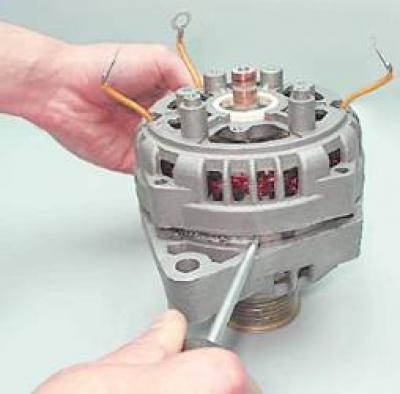
11. With a slotted screwdriver, gently push the generator covers apart.
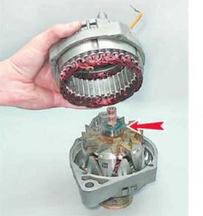
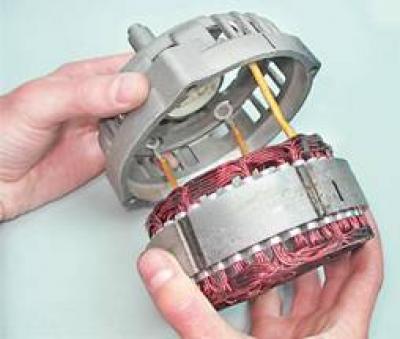
12. Disconnect the back cover together with the stator from the front cover.
Recommendation. To determine the technical condition of the rear bearing, shake from side to side and vigorously rotate its outer ring. The bearing should not have significant play, and the ring should rotate freely without jamming and extraneous noise. A defective bearing must be replaced.
13. Mark the stator with a marker (to indicate its position relative to the back cover).
14. We take out the stator from the rear cover of the generator.
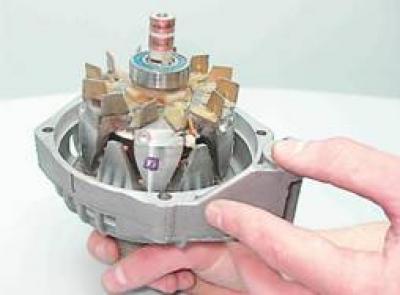
Recommendation. To determine the technical condition of the front bearing, hold the pulley with your hand, shake it from side to side and rotate the front cover. If the bearing seizes, has significant play, or makes noise when the cover is vigorously rotated, then it must be replaced.
Advice. The manufacturer recommends that the front rotor bearing be replaced along with the generator front cover, as it is rolled into the cover. But, given that the cost of the bearing is much lower than the cost of a new front cover and, especially, the generator assembly, it is advisable to press out and replace the faulty bearing.
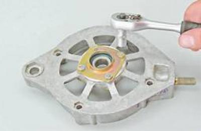
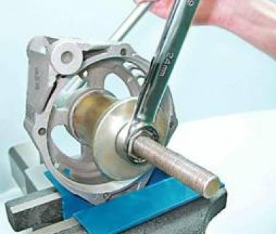
15. If it is necessary to replace the front bearing of the generator with a 24 mm socket wrench, unscrew the pulley fastening nut, holding the pulley with sliding pliers.
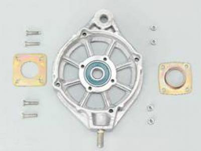
16. Remove the pulley with spring from the rotor shaft (3) and flat (2) washers, spacer (1).
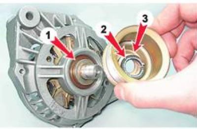
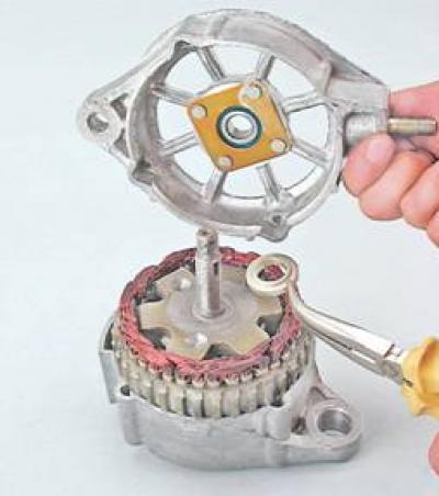
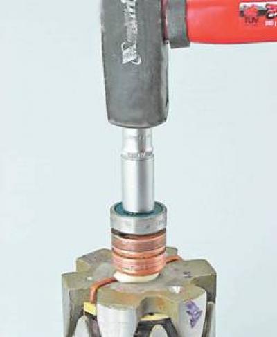
17. We screw the pulley fastening nut onto the threads of the rotor shaft (flush with end). By blows of a hammer with a rubber striker on the nut, we press the rotor out of the front bearing.
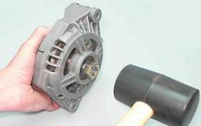
18. If it is necessary to replace the front bearing of the generator, install the front cover in a vise (The jaws of the vise must be fitted with soft metal pads).
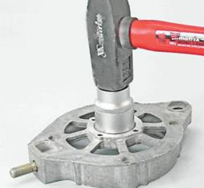
19. Selecting suitable mandrels from the cup puller set (see "Tools, fixtures and operating materials"), press the bearing out of the seat in the front cover.
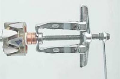
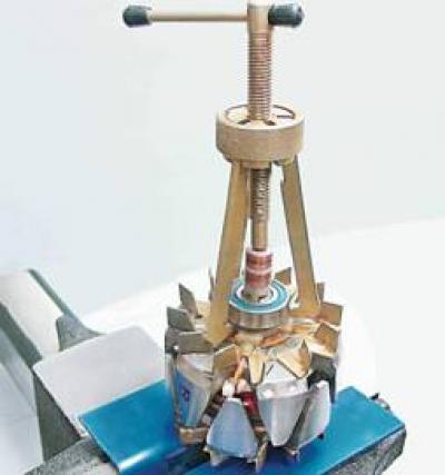
20. If it is necessary to replace the rear bearing of the generator, we fix the rotor in a vice with soft pads on the jaws. Universal puller (see "Tools, fixtures and operating materials") press the rear bearing off the rotor shaft.
Alternator test 9412.3701
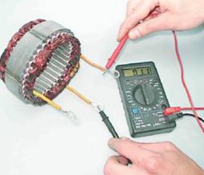
1. Check the stator windings: a) applying the ohmmeter probes to the slip rings of the rotor, we check the excitation winding for an open circuit. The resistance of a healthy excitation winding should be 5-10 ohms;
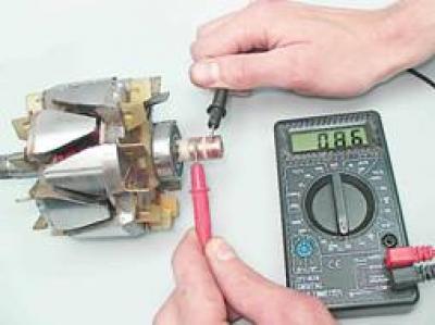
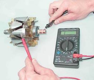
b) connecting the ohmmeter probes to any slip ring and to the rotor, we check the excitation winding for a short circuit to "mass". With a good rotor winding, the ohmmeter should show an infinitely large resistance.
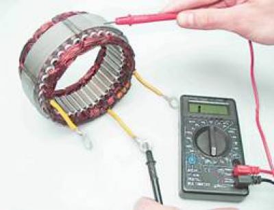
2. Check the stator windings:
A) alternately connecting the ohmmeter probes to the terminals of the stator winding, we check the winding for an open circuit. In the absence of a break, the ohmmeter will show a small electrical resistance (about 10 ohm);
b) by connecting the ohmmeter probes to any terminal of the winding and to the stator, we check the stator winding for a short circuit to "mass".
If there is no short circuit, then the ohmmeter should show infinite resistance.
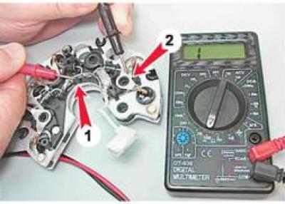
3. Check the rectifier unit:
Comment. A good semiconductor diode conducts electricity in only one direction. A diode is faulty if it does not conduct current or conducts current in both directions.
A) connect the positive lead of the ohmmeter (in diode test mode) to common bus of auxiliary diodes (1), and the negative terminal probe - to the output of the tested diode (2). A good diode should not pass current (resistance tends to infinity);
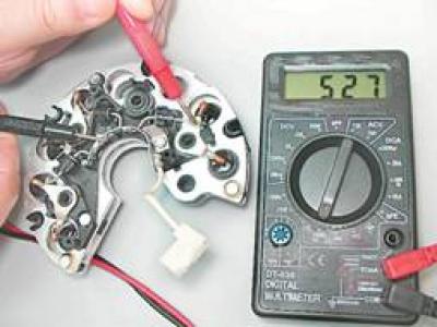
b) swap tester probes. If the diode is good, the ohmmeter should show resistance (several hundred ohms). Similarly, we check the other two auxiliary diodes;
V) we connect the probe of the negative terminal of the ohmmeter to the plate of the rectifier unit, into which the diode under test is pressed, and the probe of the positive terminal to the terminal of the diode. A good diode should not pass current (resistance tends to infinity);
G) swap tester probes. If the diode is good, then the ohmmeter should show a resistance of several hundred ohms).
Similarly, we check other power diodes.
4. Check the voltage regulator:
A) we inspect the brushes of the voltage regulator, we are convinced of their mobility. If the brushes are broken or badly worn (protrude from the brush holder by no more than 5 mm), or they are wedged in the brush holder - the voltage regulator must be replaced;
b) to check the voltage regulator, we assemble the simplest circuit (see below). TO "mass" We connect the negative terminal of the power source with a wire, and the positive terminal to its terminal. We connect the control lamp to the brushes of the voltage regulator.
Warning! When connecting wires supplying voltage to the voltage regulator, strictly observe the polarity. Incorrect wiring will damage the voltage regulator.
With a voltmeter we control the voltage supplied to the voltage regulator;
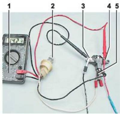
Scheme for checking the relay-regulator: 1 - multimeter (in voltmeter mode); 2 - control lamp; 3- "weight" voltage regulator; 4 - output of the voltage regulator; 5 - brushes
V) turn on the power supply and apply 13 V to the voltage regulator. The control lamp should light up, indicating that at such a voltage in the vehicle's on-board network, the excitation current will flow to the generator rotor winding;
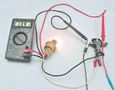
G) gradually increase the voltage until the control lamp goes out. The voltage at which the control lamp goes out should be 14.5-14.7 V.
d) reduce the applied voltage until the control lamp lights up again. The voltage at which the control lamp turned on should not be lower than 13.2 V.
5. Capacitor check:
Comment. Capacitor capacitance can only be measured with a special device. You can verify the failure of the capacitor using an ohmmeter with a measurement limit of at least 1000 kOhm.
We connect an ohmmeter to the terminals of the capacitor and observe its readings. If the capacitor is not "broken", then when connecting the device leads to it, the ohmmeter at the first moment will show a small resistance, then this resistance will increase rapidly until it stabilizes. A similar change in the readings of the ohmmeter should be repeated when the polarity of the device is changed.
A defective rotor, stator, capacitor or voltage regulator must be replaced. If one or more diodes in the rectifier unit are faulty, the unit assembly must be replaced.
Alternator assembly 9412.3701
Warning! Before pressing in the front bearing of the generator, it is necessary to check the seat of the bearing and, if necessary, restore the chamfer with a knife or scraper where the edges of the hole have remained jammed. When pressing the front bearing into the cover, the force must be transferred only to the outer ring of the bearing.
1. Selecting suitable mandrels from the cup puller set (see "Tools, fixtures and operating materials"), press the new front bearing into the seat in the front cover until it stops.
Warning! In the following operation, apply only light blows with the hammer. Strong blows can crack the cover made of brittle aluminum alloy.
2. Using a steel drift of a suitable diameter and a hammer, we restore the rolling of the bearing in the cover.
Warning! Before installing the alternator rear bearing, make sure that the rotor shaft is securely clamped in a vise. Place a wooden block of a suitable size under the rotor shaft so that the front impeller is not damaged during pressing. To avoid damage to the bearing, strikes should only be applied to the inner ring.
3. Using a piece of pipe of suitable diameter (19mm deep socket can be used) press the new bearing onto the rotor shaft until it stops.
Further assembly of the generator is carried out in the reverse order of disassembly. At the same time, we combine the marks applied to the covers and the generator stator. We finally tighten the coupling bolts evenly, crosswise, in several stages of half a turn. After tightening the bolts, we make sure that the rotor rotates easily (the rotor task may be due to the skew of the covers). Before tightening the stator winding bolts, make sure that insulating washers are installed under their heads.
Warning! When installing the voltage regulator, do not apply side forces to the brushes.