
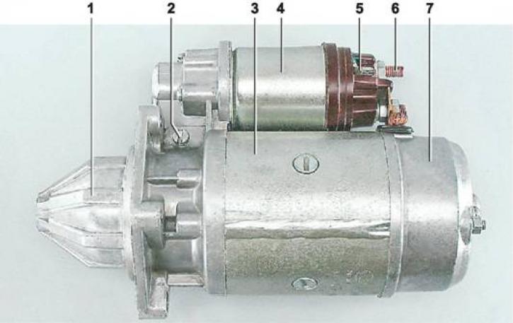
Starter 4216.3708-02: 1 - front cover; 2 - axis of the drive lever; 3 - body; 4 - starter traction relay; 5 - output "50" traction relay; 6 - contact bolt; 7 - rear starter cover
Note: Depending on the configuration, starters of models 4216.3708-02 or 5722.3708 can be installed on the car.
The starter consists of a housing, an armature with a drive gear and a freewheel, two covers and a traction electromagnetic relay. The covers and the starter housing are pulled together into a single whole by two studs passing inside. The studs are isolated from the stator windings by plastic tubes. A partition with a rubber sealing ring is installed between the front cover and the body.
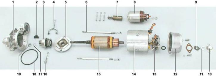
Starter parts 4216.3708-02: 1 - front cover; 2 - sealant; 3 - overrunning clutch with drive gear; 4 - drive lever; 5 - partition; 6 - tie rod; 7 - stock; 8 - starter traction relay; 9 - adjusting washers; 10 - casing of the armature shaft; 11 - lock washer; 12 - back cover of the starter; 13 - brush holder; 14 - housing with a stator; 15 - starter anchor; 16 - axis of the drive lever; 17 - retaining ring; 18 - sealing ring; 19 - restrictive ring of the gear stroke
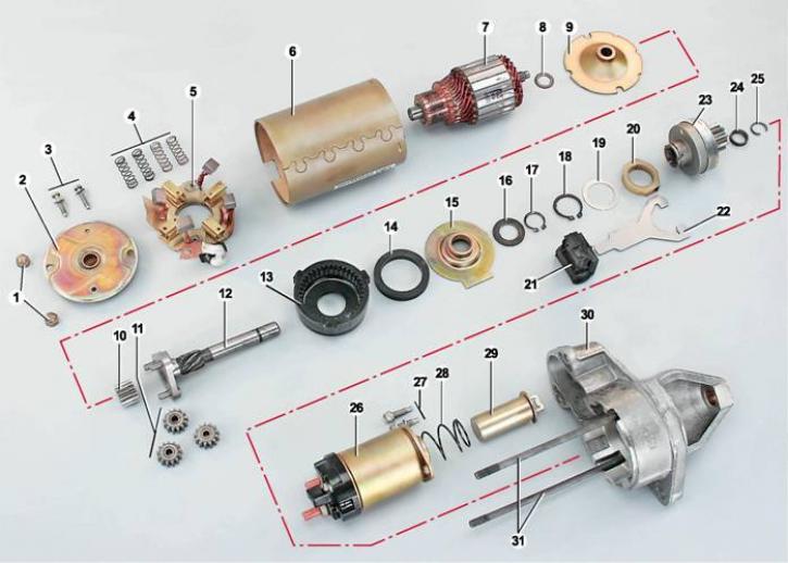
Starter details 5722.3708: 1 - nuts for fastening the rear cover; 2 - back cover; 3 - screws for fastening the brush assembly; 4 - brush springs; 5 - brush assembly; 6 - stator (with magnets); 7 - anchor; 8 - thrust washer; 9 - armature shaft support; 10 - the central gear of the gearbox; 11 - planetary (satellite) reducer gears; 12 - drive shaft; 13 - external gear of the gearbox with internal teeth; 14 - sealing ring; 15 - drive shaft support; 16 - thrust washer; 17 - retaining ring of the drive shaft; 18 - retaining ring of the drive lever coupling; 19 - washer; 20 - drive lever clutch; 21 - drive lever support; 22 - drive lever; 23 - drive; 24 - drive stroke limitation ring; 25 - locking ring of the limiter; 26 - starter traction relay; 27 - screws for fastening the traction relay; 28 - return spring; 29 - core of the traction relay; 30 - front cover; 31 - tie rods
Technical characteristics of starters 4216.3708-02/5722.3708:
| Rated voltage, V | 12 |
| Rated power, kW | 1,65/1,58 |
| Starting current in the inhibited state, A | 600/700 |
| Idle current, A | 85/80 |
| Weight, kg | 7,2/3,9 |
| Direction of rotation | right |
| Working mode | short-term with a duration of not more than 10 s |
The armature consists of a shaft, a core with a winding and a collector. The armature shaft rotates in two bronze-graphite bushings pressed into the starter covers. At the front end of the starter shaft 4216.3708-02, a drive gear is installed, rigidly connected to the overrunning roller clutch hub and the drive ring. The movement of the gear on the shaft is limited by the ring. On the inner surface of the hub, screw splines are made, which engage with the screw splines of the shaft. The bushings installed at the ends of the fork of the drive lever enter the groove of the drive ring. The other end of the lever rests on the rod of an electromagnetic traction relay, fixed to the front cover with three screws. The starter drive 5722.3708 is distinguished by the presence of a planetary gearbox.
In the back cover there is a brush holder with two insulated from the body (positive) and two closed to the body (negative) brushes. The brushes are pressed against the armature collector by springs.
Traction relay the starter motor is connected via the enable relay located in the engine compartment on the right mudguard (in the variant version of the car, the starter enable relay may be absent).
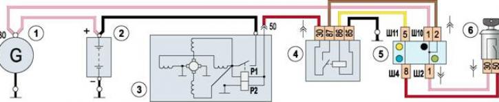
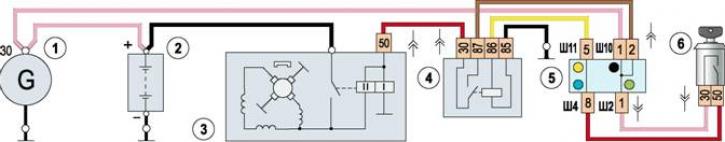
Starter wiring diagram 4216.3708-02: 1 - generator; 2 - battery; 3 - starter; 4 - starter enable relay*; 5 - mounting block; 6 - switch (lock) ignition
Starter wiring diagram 5722.3708: 1 - generator; 2 - battery; 3 - starter; 4 - starter enable relay; 5 - mounting block; 6 - switch (lock) ignition
* in the version of the car, the starter enable relay may be absent
The traction relay is used to engage the starter drive gear with the flywheel ring and to close the power circuit of the armature and stator windings. Contact bolts are installed in the relay cover. One bolt is connected by wire to the positive battery terminal, and the other to the stator and relay windings. When the ignition key is turned to position II ("starter"), voltage is applied to the output "50" traction relay covers. In this case, the resulting magnetic field draws the armature. The contact plate closes the contact bolts, and the rod acts on the drive lever. The lever, moving the drive gear, engages it with the ring gear of the engine flywheel. The stator and armature supply current flows through the closed relay contacts. As a result of the interaction of magnetic fields, the starter armature begins to rotate along with the hub and the outer ring of the overrunning clutch. In this case, the overrunning clutch rollers are wedged between the outer and inner rings of the clutch. Torque from the armature shaft is transmitted through the clutch and drive gear to the flywheel crown. After starting the engine, the speed of the gear begins to exceed the speed of the starter armature shaft. The clutch rollers are wedged and the torque from the flywheel is not transmitted to the starter armature shaft. When the key is returned to position I ("ignition") the power supply circuit of the windings of the traction relay opens and, under the action of the return spring of the relay, the armature returns to its original position, opening the contacts and disengaging the drive gear.