
Examination
To perform the work you will need a multimeter.
1. Remove the starter (see "Starter - removal and installation").
2. We clean the outer surface of the starter from dirt.
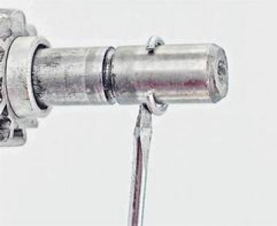
3. To check the traction relay, disconnect the output of the starter windings from the contact bolt (see below, "Repair"). Connecting the output "50" relay with a positive battery terminal, and the starter housing with a negative one. In this case, for a working relay, the armature will push the drive gear A into the window of the front cover, and the contact bolts are closed.
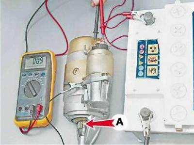
The resistance shown by the ohmmeter should tend to zero.
4. To check the armature and stator windings, remove the back cover of the starter (see below, "Repair").
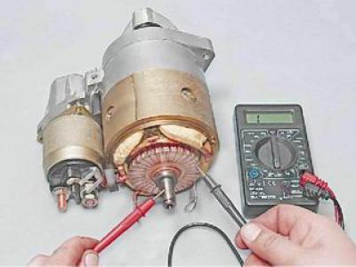
5. Having connected one probe of the ohmmeter to the case, we alternately connect the other to the terminals of the stator windings, checking that they are not shorted to the case.
In the absence of a short circuit, the ohmmeter should show a resistance of at least 10 kOhm.
6. Having connected the ohmmeter probes to the terminals of the stator windings, we check them for an open circuit.
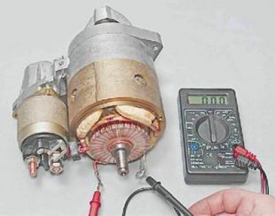
If the resistance tends to infinity, the winding has broken.
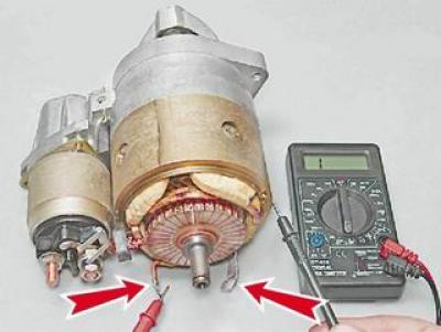
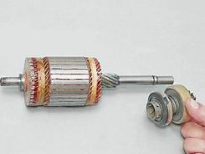
7. Having connected one probe of the ohmmeter to the body or armature shaft, we connect the other alternately to the armature contact plates, checking the armature windings for short circuit "mass".
In the absence of a short circuit, the ohmmeter should show a resistance of at least 10 kOhm.
Repair
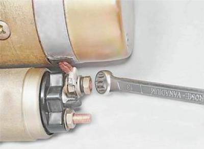
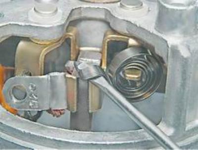
1. socket wrench by 13 mm loosen the nut and remove the stator winding terminal from the contact bolt.
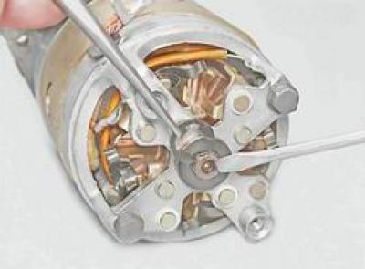
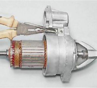
2. Using a slotted screwdriver, unscrew the three screws securing the traction relay.
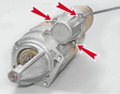
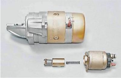
3. Remove the traction relay with a rod and a spring.
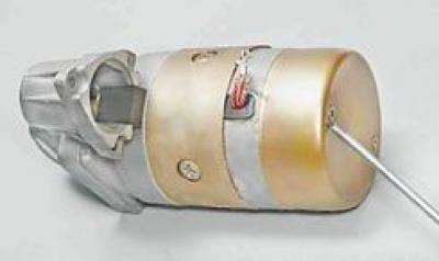
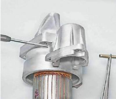
4. Using a slotted screwdriver, unscrew the two screws securing the rear cover casing and remove the casing.
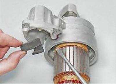
5. Using a slotted screwdriver, unscrew the two screws A and B fastening the stator windings and the leads of the corresponding brushes to the brush assembly.
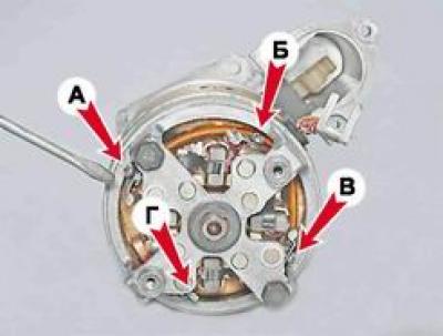
screws A and IN the brush jumper is fixed. screw G the brush outlet is attached.
6. With a screwdriver, pry off and remove the lock and the shim located under it.
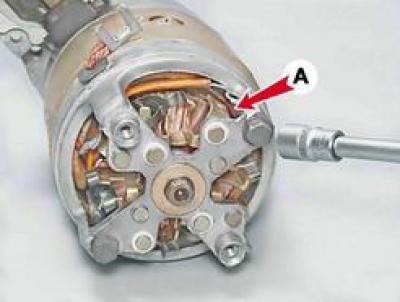
7. socket wrench by 10 mm unscrew the two bolts. On the bolt located next to the tire A (connecting stator winding) put on an insulating tube.
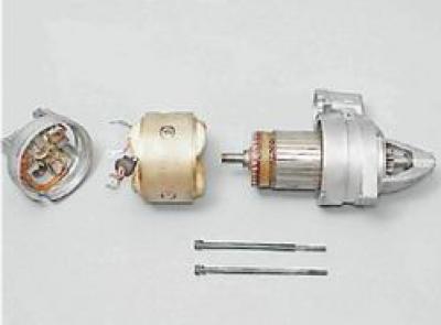
8. Disconnect the back cover and the front cover from the body along with the anchor.
9. We unscrew the two remaining screws securing the brush leads. A jumper is fixed on one of the screws.
10. With a screwdriver, pry off and remove the four springs and remove the brushes from the guides.
11. Use pliers to remove the cotter pin holding the lever axis.
12. Push out the axle with a beard.
13. Prying with a screwdriver, take out the rubber seal.
14. Using a screwdriver, we press the lever fork and disengage it from the overrunning clutch ring.
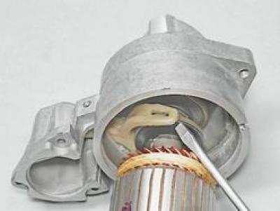
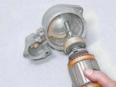
15. We take out the anchor.
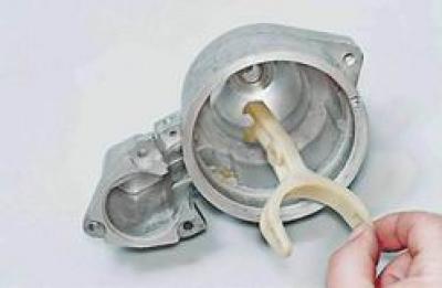
16. Remove the lever from the cover.
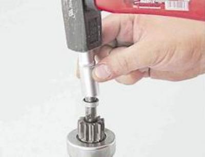
17. Having rested the armature shaft on a wooden block, with a suitable mandrel we press the restrictive ring from the retaining ring.
18. Prying with a slotted screwdriver, remove the retaining ring from the shaft.
19. Remove the restrictive ring and the overrunning clutch with the drive gear from the armature shaft.
Assembly
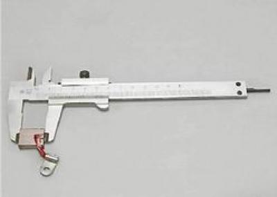
1. We wash the starter parts with white spirit or kerosene, blow it with compressed air. Checking the condition of the parts. Covers and body must be free of cracks. Gear teeth should not show significant wear. The gear should easily rotate relative to the hub in only one direction - in the direction of rotation of the armature. On the surfaces of the splines and pins of the shaft there should be no burrs, nicks or wear marks. There must be no burns on the working surface of the collector. We remove small burns with fine-grained sandpaper. The brushes must move freely in the grooves of the brush holders. brush holders "positive" brushes should not have a short circuit with "weight". Worn to a height of less than 12 mm, the brushes are replaced with new ones.
2. Lubricate with engine oil the bearing surfaces and splines of the armature shaft, the splines of the overrunning clutch hub, the bearing bushings in the starter covers and the axis of the drive lever. Lubricate the drive ring of the overrunning clutch hub with grease.
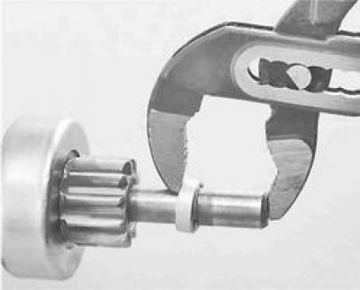
3. We install an overrunning clutch with a drive gear on the armature shaft.
4. We put the limiting ring of the gear travel on the shaft so that the smaller diameter of the inner conical surface of the ring faces the gear. We install a retaining ring in the groove of the shaft, crimp it and press the restrictive ring onto it with sliding pliers, if necessary, sinking the retaining ring into the groove with a slotted screwdriver.
5. Next, assemble the starter in reverse order.
6. Before installing the casing, we check the axial play of the armature shaft, which should be no more than 0.5 mm. If necessary, adjust it by installing shims on the armature shaft (see above, "Repair", item 6).
7. Install the casing.
8. Install and connect the traction relay.