




The service brake system is designed to reduce the speed of the vehicle, up to its complete stop and to hold the vehicle stationary for a short time.
The service brake system is dual-circuit, diagonal, with hydraulic drive, consists of a main brake cylinder with a vacuum booster, four wheel brake mechanisms and a fluid pressure regulator in the rear brake mechanisms. The front wheel brake mechanisms are disc, non-ventilated, the rear ones are drum.
Each of the vehicle circuits includes brake mechanisms of two wheels: one front and one rear, located diagonally on the vehicle. One circuit includes brake mechanisms of the front right and rear left wheels, and the second - brake mechanisms of the front left and rear right wheels. If one of the circuits fails, the second circuit, although with less efficiency, will ensure that the vehicle stops.
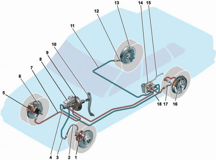
Service brake system: 1 - front left wheel brake mechanism; 2, 6, 12, 17 - brake hoses; 3, 7, 11, 18 - brake pipes; 4 - master brake cylinder; 5 - front right wheel brake mechanism; 8 - master brake cylinder reservoir; 9 - vacuum booster; 10 - brake pedal; 13 - rear right wheel brake mechanism; 14 - fluid pressure regulator in the rear wheel brake mechanisms; 15 - brake fluid pressure regulator lever for rear wheels; 16 - rear left wheel brake mechanism
The fluid pressure regulator limits the flow of fluid to the rear brakes when the rear axle is underloaded, thereby preventing the rear wheels from locking and the rear axle from skidding during sudden braking. The regulator body has a control hole covered with a plastic plug. Fluid leaking from this hole indicates that the regulator rings are not tight.
[The information can be read on the website: VazBook]
To reduce the force applied by the driver to the brake pedal, a vacuum booster is installed in the brake system drive, which operates by using the vacuum created in the intake manifold of the running engine.
Warning! Do not turn off the engine until the vehicle has come to a complete stop.
A brake fluid reservoir is installed on the main brake cylinder body. A brake fluid insufficiency sensor is installed in the reservoir cap. When the fluid level in the reservoir drops dangerously, the sensor turns on the control lamp on the instrument panel.