
Attention! The direction of the headlight beams should be such that the road in front of the car is well lit, and the drivers of oncoming vehicles are not blinded when the dipped beam is turned on.
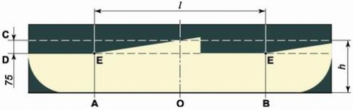
Screen layout for headlight adjustment: A - a vertical line indicating the location of the dipped beam lamp of the left headlight; B - a vertical line indicating the location of the dipped beam lamp of the right headlight; C - a horizontal line indicating the location of the dipped beam headlights; D - line indicating the height of the horizontal border of the beams of light; O - centerline; l is the distance between the dipped beam headlights; h - the distance from the surface of the site on which the car is installed to the dipped beam headlights
You will need a flat, vertical surface to do the job (screen) size - 2x1 m and assistant (or a load weighing 75 kg).
Execution sequence
1. We install a fully charged and equipped (spare wheel, tool, jack) car on a flat horizontal platform at a distance of 5 m perpendicular to the screen (length - 2 m, height - 1 m).
2. Check and, if necessary, set the required tire pressure (see "Tires - pressure check").
3. Apply markup on the screen (see diagram). The upper horizontal line C is drawn at the height of the center of the headlights from the surface of the site, the second line D is 75 mm lower than the first. The vertical line O coincides with the plane of symmetry of the car, and lines A and B run parallel to line O through points E corresponding to the centers of the headlights. The distance / between the dipped beam headlights for this vehicle is 936 mm.
4. Set the headlight hydrocorrector control handle to position I (far right) (see "The block of regulators of the hydrocorrector of headlights and illumination of devices").
5. An assistant sits on the driver's seat or a load is placed.
6. Turn on the dipped beam.
7. Close one headlight with a piece of cardboard or other suitable object.
8. By turning the adjusting screw located on the rear wall of the headlight on the side of the direction indicators, we combine the upper horizontal border of the light beam with the bottom line on the screen (E-E).
9. Turning the second adjusting screw, we combine the break point of the upper border of the light beam with the vertical line point E.
10. Similarly, we adjust the other headlight.