




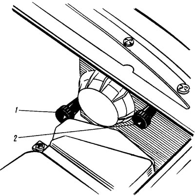
Figure 147. Headlight adjustment screws: 1 - screw for adjusting the light beam in the horizontal direction; 2 - screw for adjusting the light beam in the vertical direction
A fully fueled and equipped vehicle with a load of 75 kgf on the driver's seat is placed on a flat horizontal surface 5 m from a smooth wall or any screen (shield size about 2X1 m) so that the car's axis is perpendicular to it. Before marking the screen, make sure that the air pressure in the tires is normal, and then rock the car from the side so that the suspension springs are installed.
They draw on the screen (figure 148) vertical lines: axial O and lines A and B passing through points E corresponding to the centers of the headlights. These lines must be symmetrical relative to the axial line of the car. At a height corresponding to the distance of the centers of the headlights from the floor, line 1 is drawn and below it by 65 mm line 2 of the centers of the light spots. The headlight hydraulic corrector handle is installed (if it exists) on the instrument panel to the position corresponding to the load of the car with one driver.
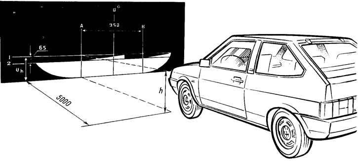
Figure 148. Headlight adjustment diagram
Turn on the low beam headlights
Sequentially, first for the right headlight (the left one is covered with a piece of cardboard or dark fabric or turned off), and then for the left (the right one is closed) adjust with screws 1 (see figure 147) and 2 light beams of headlights. In correctly adjusted headlights, the upper border of the light spots should coincide with line 2 (see figure 148), and the points of intersection of the horizontal and inclined sections of the light spots with lines A and B.
Headlight Hydraulic Corrector
If the headlight tilt angle has increased and the adjusting screw on the headlight unit cannot bring it back to normal, then check for fluid leaks from the cylinders or tubes of the hydraulic corrector. Remove the actuator cylinders from the headlight units and check the working stroke of the rods, which should be (7±0.5) mm.
The design of the hydraulic corrector is non-separable and in case of damage it is replaced as a whole, together with the cylinders and tubes. To replace, disconnect the tube clamps from the wire fastening brackets. Remove the handle from the main cylinder and unscrew the nut fastening it to the instrument panel. Disconnect the actuator cylinders from the headlights and push them with the seal into the car interior. Install the new hydraulic corrector in the reverse order.
(The text is published on the portal: «www.VAZbook.ru»)