




Windshield and headlight washer circuit diagram
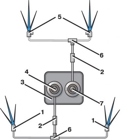
1 – headlight washer jets; 2 – check valves; 3 – feed tank; 4 – headlight washer pressure pump; 5 – windshield washer jets; 6 - tees; 7 – Windshield washer pressure pump
Windshield washer pressure pump
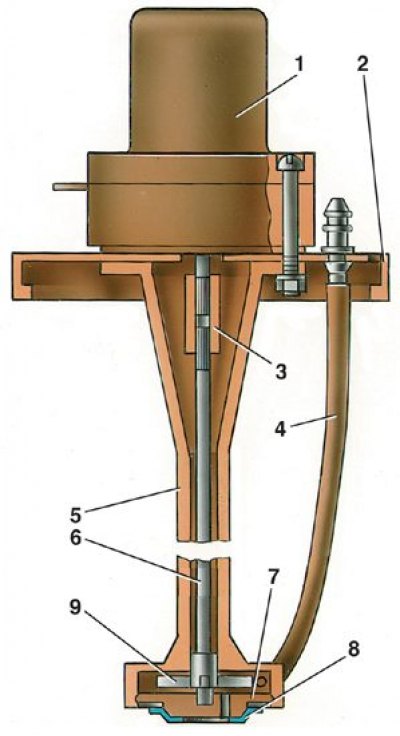
1 – electric motor; 2 – cover of the feed tank; 3 – coupling; 4 – liquid supply pipe; 5 – pump body; 6 – rotor shaft; 7 – rotor shaft support; 8 – rim with filter mesh; 9 – rotor
1. Disconnect the electrical wires from the electric motors of injection pumps 4 and 7 (see fig. Windshield and headlight washers diagram) and remove the tubes from the fittings.
2. Turn the lid 2 (see fig. Windshield washer pressure pump) with electric motor 1 counterclockwise and remove them from the feed tank assembly with the injection pump.
[The text is on the website vazbook]
3. Perform installation in reverse order.