
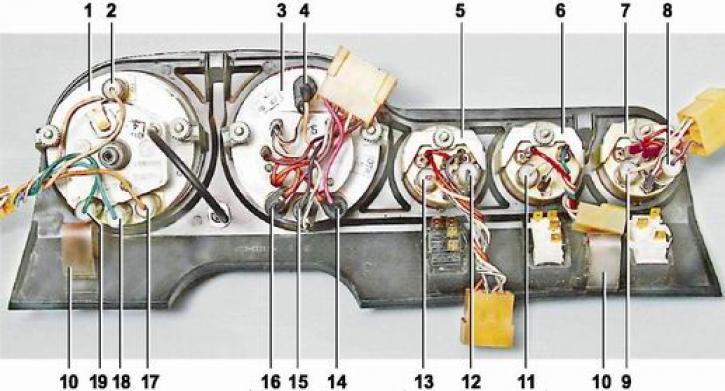
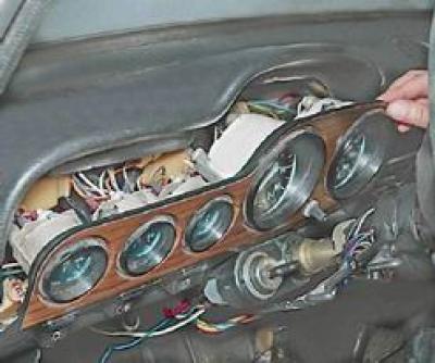
Location of lamps and appliances on shield: 1 - speedometer; 2 - speedometer illumination lamp (AMH12-4 (W4W); 3 - tachometer; 4 - tachometer illumination lamp (AMH12-4 (W4W); 5 - oil pressure indicator; 6 - liquid temperature gauge in the cooling system; 7 - fuel gauge; 8 - fuel reserve control lamp (AMH12-3 (W3W); 9 - fuel level indicator lamp (AMH12-4 (W4W); 10 - shield fastening bracket; 11 - lamp for backlighting the liquid temperature gauge in the cooling system (AMH12-4 (W4W); 12 - control lamp of insufficient oil pressure (AMH12-3 (W3W); 13 - oil pressure indicator lamp (AMH12-4 (W4W); 14 - control lamp for turning on the parking brake (AMH12-3 (W3W); 15 - battery charge control lamp (AMH12-3 (W3W); 16 - control lamp for covering the air damper of the carburetor (AMH12-3 (W3W); 17 - control lamp for switching on outdoor lighting (AMH12-3 (W3W); 18 - control lamp for turning on the direction indicators (AMH12-3 (W3W); 19 - control lamp for switching on the high beam (AMH12-3 (W3W)
Removing
1. We prepare the car for work (see "Vehicle preparation for maintenance and repair").
2. Disconnect the wire from the negative battery terminal (see "Battery - removal and installation").
3. Remove the steering column covers (see "Steering shaft casings - removal and installation").
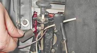
4. From the bottom of the dashboard, disconnect the wire from the switch for the control lamp to cover the air damper.
5. Prying with a screwdriver, wring out the top of the shield and disengage it from the panel.
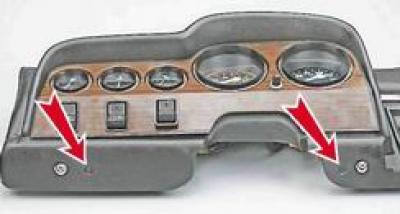
Note: In the event that the top of the shield cannot be squeezed out, the bottom of the instrument panel in special places (shown by arrows) pierce two holes with an awhp a thin screwdriver or a metal rod, we squeeze out the spring clips and take out the bottom of the shield.
6. We take out a guard from the panel of devices.
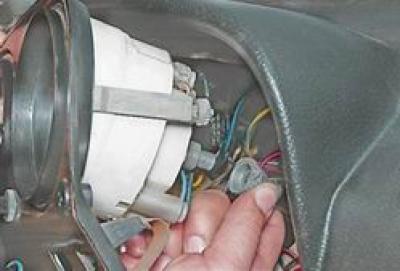
7. Pulling out the shield as much as possible, unscrew the corrugated nut fastening the speedometer cable by hand and disconnect the cable.
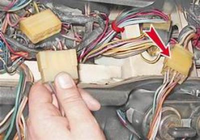
8. Disconnect the two pads of the shield wiring harness from the instrument panel wiring harness.
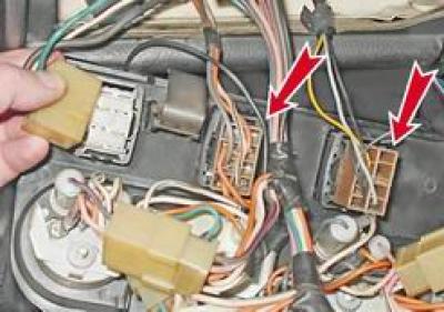
9. Having previously marked or remembered the location, disconnect the wire blocks from the three key switches.
10. Remove the shield.
Installation
Installation of the instrument panel is carried out in reverse order.