




Contents: Removal ↓ Installation ↓
Removal
1. Prepare the vehicle for operations (see "Preparing a car for maintenance and repair").
2. Disconnect the wire from the negative terminal of the battery (see "Battery - Removal and Installation").
3. Remove the upper steering shaft cover (see "Steering shaft covers - removal and installation").
4. Remove the instrument panel (see "Instrument cluster model 2105 - removal and replacement of lamps").
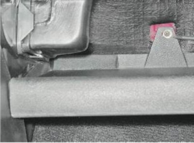
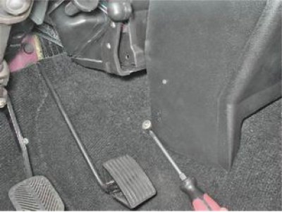
5. Using a Phillips screwdriver, unscrew the screw securing the front storage shelf.
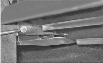
6. Using the same tool, unscrew the screw securing the shelf on the left side.
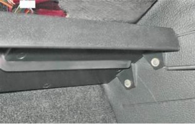
7. Unscrew the two screws securing the shelf on the right side.
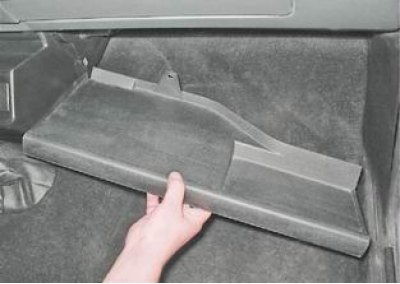
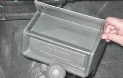
8. Remove the shelf.
9. Using the same tool, unscrew one screw of the lower fastening of the radio panel on the left and right sides.
10. Unscrew the two screws of the upper panel mount.
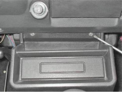
11. Remove the radio panel.
12. After opening the lid, use a Phillips screwdriver to unscrew the two screws securing the glove box body.
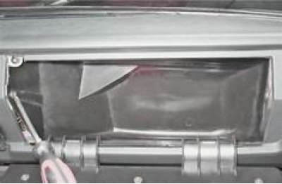
13. Remove the glove box housing from the instrument panel.
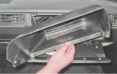
14. Using a short Phillips screwdriver, unscrew the three screws securing the instrument panel insert (the photo shows two screws).
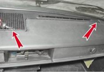
15. Using a slotted screwdriver, pry up and remove the heater control lever handles.
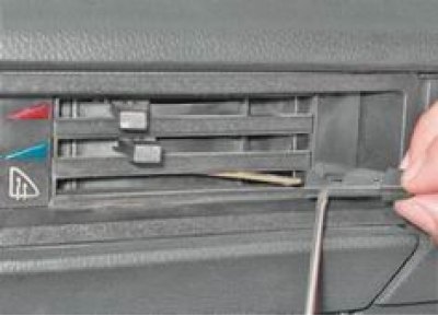
16. Using the same tool, pry up the instrument panel trim and remove it.
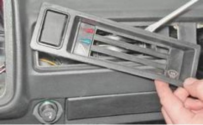
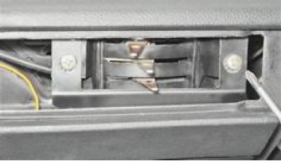
17. Using a Phillips screwdriver, unscrew the two screws securing the interior ventilation and heating control unit.
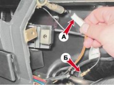
18. Disconnect the wiring block A from the glove compartment light and disconnect the ground wire B.
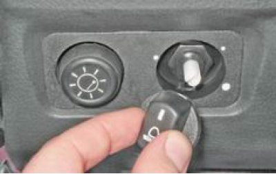
19. Pull and remove the handle from the headlight range control.
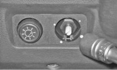
20. With a socket wrench by 21 mm we unscrew the hydraulic corrector mounting nut and push it inside the instrument panel.
(The article is copied from the website: «www.VazBook.ru»)
21. Disconnect the instrument lighting control wire connectors.
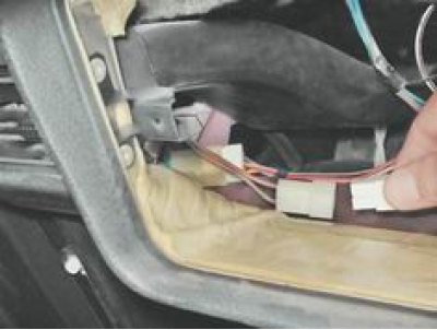
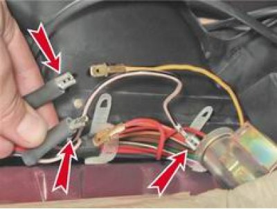
22. Having marked the wires, we disconnect them from the cigarette lighter.
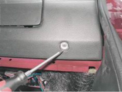
23. Using a Phillips screwdriver, unscrew the four screws that secure the lower mounting of the instrument panel to the body (the photo shows the screw of the right lower fastening).
24. Through the hole for installing the instrument panel with a socket or open-end wrench by 10 mm we unscrew the two nuts of the upper instrument panel mount.
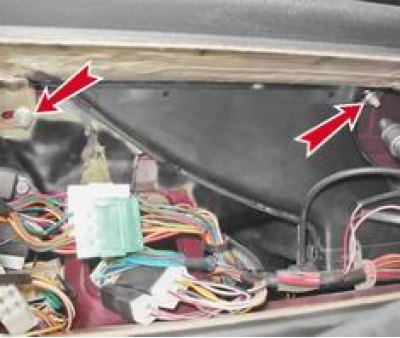
25. Using the same tool, through the hole for installing the glove box housing, unscrew two more nuts of the upper instrument panel mount and remove it.
Installation
The installation of the instrument panel is carried out in the reverse order.