
English Русский
Български
Беларускі
Український
Српски
Hrvatski
Română
Polski
Slovenský
Magyar
| Articles | Contacts | Sitemap |   
Repair and maintenance Lada Repair and maintenance Mazda Repair and maintenance Mitsubishi Repair and maintenance Toyota Repair and maintenance Land Rover Repair and maintenance Hyundai Repair and maintenance Nissan
VAZbook.ru


Main     1111   2101   2105   2106   2107   2109   2110   2115   2121  
VAZ-2110 (1995-2007) VAZ-2112 (1999-2007)
  • Main
  • «Lada»
  • VAZ-2110
  • Body
  • Interior
  • Removal and installation the instrument panel

Removal and installation the instrument panel (VAZ-2110)

            0

Contents: Removal ↓ Installation ↓
Note. The repair manuals for VAZ 2110 family cars indicate that in order to remove the instrument panel, it is necessary to disassemble it almost completely. This is not always convenient, so this section discusses removing the instrument panel without disassembling it.


Removal


1. Prepare the car for repair work.

2. Disconnect the terminal from the negative terminal of the battery.

3. Remove the decorative steering column trims.

4. Remove the steering wheel without removing the horn contact plate.

5. Remove the right and left steering column switches without removing their connector.

6. Disconnect the ends of the two wires from the steering column switches.

7. Using a slotted screwdriver, remove the headlight range control knob.
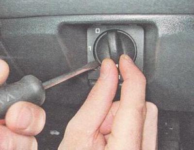
7. Using a slotted screwdriver, remove the headlight range control knob.


8. Using a 21 mm deep-head socket wrench, unscrew the headlight range control mounting nut and press its rod into the hole in the instrument panel.
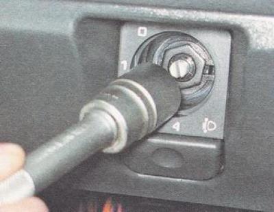
8. Using a 21 mm deep-head socket wrench, unscrew the headlight range control mounting nut and…


9. Open the cover of the mounting block.


10. In the niche of the relay and fuse box, use a Phillips screwdriver to unscrew the screw securing the left inner bracket of the instrument panel.
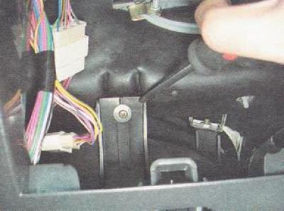
10. In the niche of the relay and fuse box, use a Phillips screwdriver to unscrew the screw…


11. Disconnect the ignition switch wire connector (1) and use a Phillips screwdriver to unscrew the screw securing the diagnostic connector bracket (2).
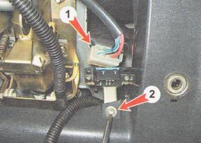
11. Disconnect the ignition switch wire connector (1) and use a Phillips screwdriver to unscrew the…


12. Disconnect the ends of the two wires from the brake light limit switch (located on the brake pedal bracket).
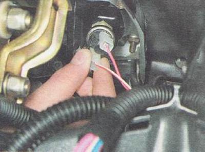
12. Disconnect the ends of the two wires from the brake light limit switch (located on the brake…


13. Using a Phillips screwdriver, unscrew the two screws securing the left trim of the center console. By sliding the trim back, we disengage its front part from the bracket and remove the trim.
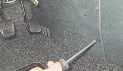

13. Using a Phillips screwdriver, unscrew the two screws securing the left trim of the center…


14. Using a 10 mm socket wrench, unscrew the nut securing the panel to the console bracket (the tips of three ground wires are installed under the nut).
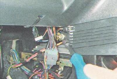
14. Using a 10 mm socket wrench, unscrew the nut securing the panel to the console bracket (the…


15. Using a Phillips screwdriver, unscrew the screw securing the instrument panel and air duct, holding the screw nut with an 8 mm wrench if necessary.
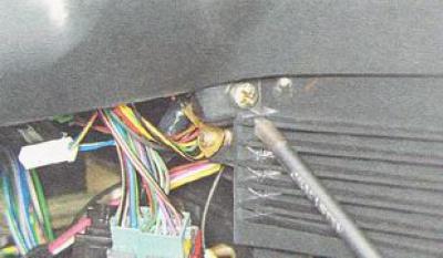
15. Using a Phillips screwdriver, unscrew the screw securing the instrument panel and air duct,…


Recommendation: The next part of the job requires disconnecting the wire connectors located under the instrument panel. Although these connectors have different shapes, different colors and different numbers of terminals, to simplify assembly, mark the paired connectors with a marker before disconnecting them.


16. After pulling out the retaining clip, disconnect the instrument panel wire connector.
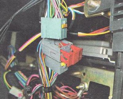
16. After pulling out the retaining clip, disconnect the instrument panel wire connector.


17. Using a thin slotted screwdriver, press the retainer and disconnect the two connectors coming from the immobilizer sensor.
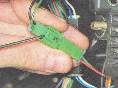
17. Using a thin slotted screwdriver, press the retainer and disconnect the two connectors coming…


18. Using a slotted screwdriver, unscrew the three screws securing the right console trim.
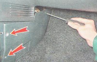
18. Using a slotted screwdriver, unscrew the three screws securing the right console trim.


19. Using a 10 mm socket wrench, unscrew the right nut securing the instrument panel to the console bracket.
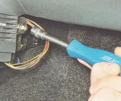
19. Using a 10 mm socket wrench, unscrew the right nut securing the instrument panel to the console…


20. Disconnect the cigarette lighter connectors.
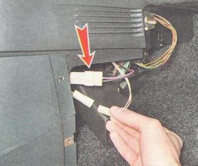
20. Disconnect the cigarette lighter connectors.


21. Disconnect the wire connector from the fog light relay.
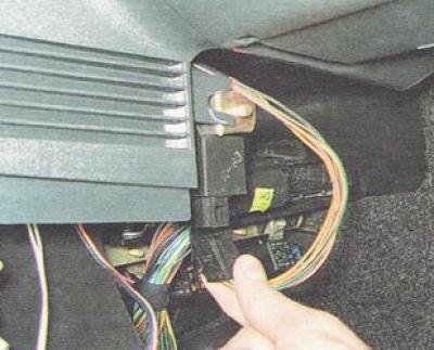
21. Disconnect the wire connector from the fog light relay.


22. In the recess of the glove compartment, use a Phillips screwdriver to unscrew the screw securing the right inner bracket of the instrument panel.
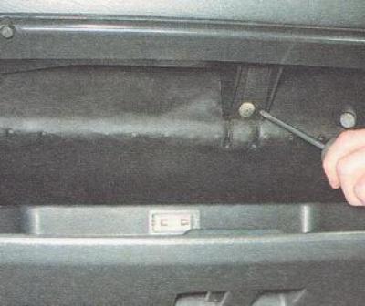
22. In the recess of the glove compartment, use a Phillips screwdriver to unscrew the screw…


23. Using a Phillips screwdriver, unscrew the right...
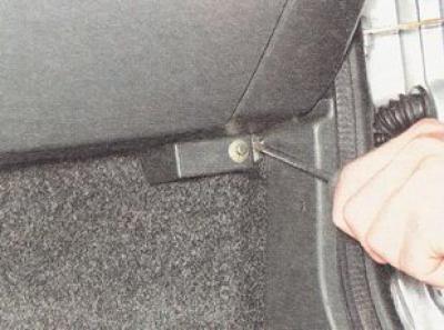
23. Using a Phillips screwdriver, unscrew the right...


...and the left screws for the lower mounting of the instrument panel.
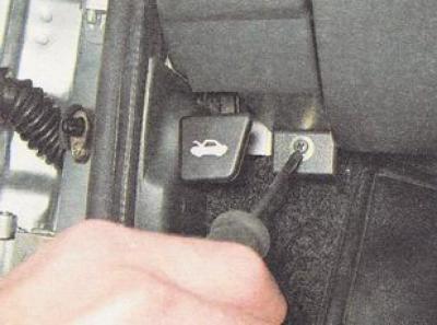
...and the left screws for the lower mounting of the instrument panel.


24. Remove the seal from the flange of the front left pillar.
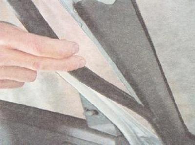
24. Remove the seal from the flange of the front left pillar.


25. Using a wide slotted screwdriver, pry up and remove the plastic holders of the trim from the holes in the rack and remove the trim from the rack.
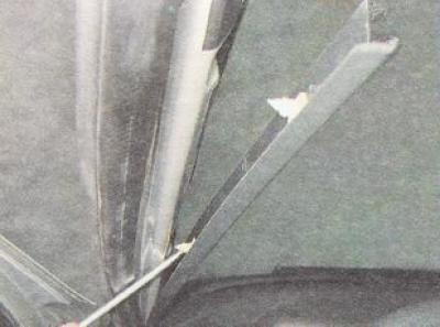
25. Using a wide slotted screwdriver, pry up and remove the plastic holders of the trim from the…


26. Similarly, remove the right windshield pillar trim.

27. Using a thin slotted screwdriver, pry from both sides of the instrument panel and remove the ventilation grilles for blowing air from the front door windows.
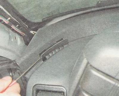
27. Using a thin slotted screwdriver, pry from both sides of the instrument panel and remove the…


28. Using a 10 mm socket wrench, unscrew the two nuts of the upper instrument panel mount, located under the ventilation grilles.
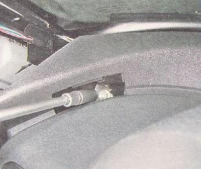
28. Using a 10 mm socket wrench, unscrew the two nuts of the upper instrument panel mount, located…


29. Move the instrument panel 15-20 cm into the passenger compartment.

30. Behind the instrument panel, disconnect nine wire connectors (seven connectors (1) near the left door pillar and two connectors (2) near the steering column).
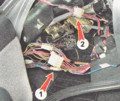
30. Behind the instrument panel, disconnect nine wire connectors (seven connectors (1) near the…


31. After making sure that all instrument panel wire connectors are disconnected from the on-board electrical system connectors, remove the instrument panel from the vehicle interior through the opening of the left front door.

Installation


We install the instrument panel and all previously removed parts on the car in the reverse order.


This article is available at russian, bulgarian, belarusian, ukrainian, serbian, croatian, romanian, polish, slovak, hungarian
The text was reviewed by the specialist: Grigory Vologodtsev

Share with friends:

Previous articles
VAZ-2110: Interior
Next articles

Removal and installation sun visors
Removal and installation the interior rearview mirror
Removal and installation the floor tunnel trim
Removal and installation the front seat
Removal and installation the rear seat

More articles from other manuals on VAZ cars:
➠ Removal and installation the instrument panel VAZ-1111 (1988-1996)
➠ Instrument panel — device and removal VAZ-2101 (1970-1983)
➠ Instrument panel VAZ-2105 (1979-2010)
➠ Instrument panel VAZ-2106 (1976-2006)
➠ Instrument panel — removal and installation VAZ-2107 (1982-2012)
Link in different formats to this page


Visitor comments

No comments yet


How much will 25 + 32 ?


VAZ-2110 (1995-2007) 
  • General information
  • Vehicle description
  • Specifications
  • User manual
  • Maintenance
  • Operation and maintenance
  • Tips for car owner
  • Power unit
  • Engine repair
  • Supply system
  • Control system
  • Cooling system
  • Exhaust system
  • Transmission
  • Clutch
  • Car gearbox
  • Front wheel drives
  • Chassis
  • Suspension and wheels
  • Steering
  • Brake system
  • Body
  • Exterior
  • Interior
  • Doors and glass
  • Tailgate
  • Ventilation and heating
  • Electrical equipment
  • Equipment and devices
  • Headlights and lighting
  • Engine electrics
  • Electrical circuits


VAZ-2112 (1999-2007) 
  • General information
  • Operation and maintenance
  • Power unit
  • Engine repair
  • Supply system
  • Control system
  • Cooling system
  • Exhaust system
  • Transmission
  • Clutch
  • Car gearbox
  • Front wheel drives
  • Chassis
  • Wheels and tires
  • Car suspension
  • Steering
  • Brake system
  • Body
  • Exterior
  • Interior
  • Doors and glass
  • Tailgate
  • Ventilation and heating
  • Electrical equipment
  • Equipment and devices
  • Headlights and lighting
  • Engine electrics
  • Electrical circuits


VAZbook.ru © 2017 · Mobile version · Contact with administration · Sitemap: EN BG BY UA RS HR RO PL SK HU · Site search · News and articles VAZ-1111 · VAZ-11113 · VAZ-2101 · VAZ-21011 · VAZ-2104 · VAZ-2105 · VAZ-21051 · VAZ-2106 · VAZ-21061 · VAZ-2107 · VAZ-21099 · VAZ-2109 · VAZ-2108 · VAZ-2110 · VAZ-2112 · VAZ-2114 · VAZ-2115 · VAZ-2121 · VAZ-21213 · VAZ-21214 ·
The site stores technical data using cookies to improve the service.