
2. Disconnect the wire from the negative battery terminal (see "Battery - removal and installation").
Wiper Relay Replacement (PC514)
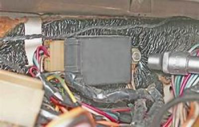
The wiper relay is located in the passenger compartment on the left side of the body under the instrument panel and is designed to provide intermittent operation.
You will need two plastic upholstery holders to complete the job.
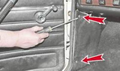
1. Having removed the seal from the flanging of the front pillar of the driver's door, use a screwdriver to pry off the sidewall upholstery and remove it, removing the two holders from the holes in the sidewall (holders are usually destroyed). We bend the soundproofing.
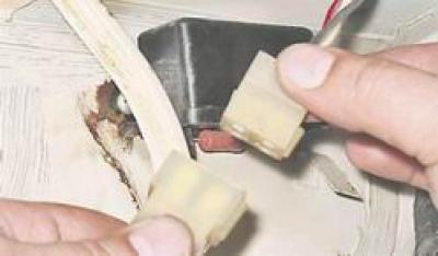
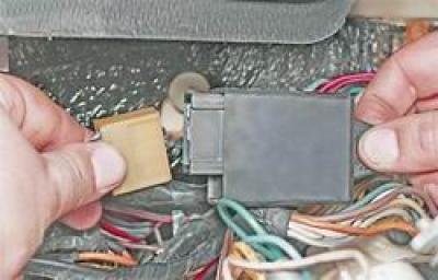
2. Disconnect the relay wiring harness from the harness. The connector is located at the bottom of the instrument panel.
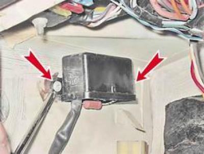
3. Using a Phillips screwdriver, unscrew the two screws and remove the relay.
4. Install all removed parts in reverse order. We fix the upholstery of the sidewall with new holders.
Replacing the relay-interrupter of the direction indicator and alarm (231.3747 or 23.3747)
The relay-breaker is installed on the bulkhead of the engine compartment behind the instrument panel. The relay is designed to receive an intermittent light signal of the direction indicators both in the alarm mode and in the direction indication mode and to monitor the serviceability of the direction indicator lamps. When the lamp burns out, the relay doubles the flashing frequency.
1. Remove the instrument panel (see "Instrument panel - removal and installation").
2. socket wrench by 10 mm Loosen the relay mounting nut. Under the nut are the tips of two "massive" wires.
3. Disconnect the wiring block from the relay.
4. Install all removed parts in reverse order.
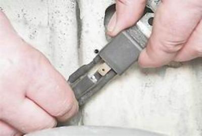
Replacing the headlight relay (90.3747-10 or 113.3747-10)
Two relays for switching on the low and high beams are installed in the engine compartment on top of the right mudguard.
1. Using a Phillips screwdriver, unscrew the fastening screw and remove the relay. Under the high beam relay mounting bracket is a mass "wires".
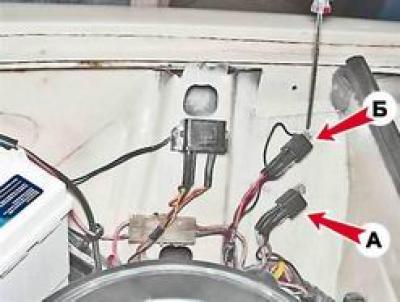
A - high beam relay, B - low beam relay.
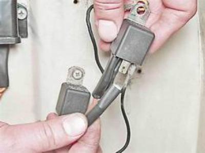
2. Having marked or remembered the location of the wires, disconnect them from the relay outputs. For convenience, you can sequentially disconnect the wires, immediately connect them to a working relay.
3. Install all removed parts in reverse order.
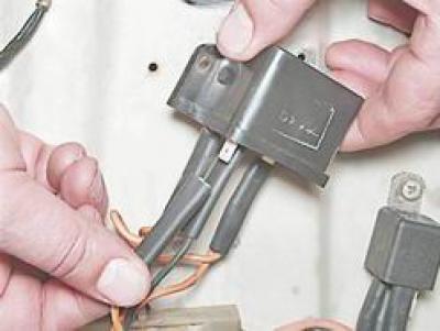
Replacing the Battery Warning Lamp Relay (PC702)
The relay is located in the engine compartment on top of the right mudguard. The relay is used to turn on the warning lamp on the instrument panel in the event of a malfunction in the battery charging circuit. When the ignition is on, the control lamp is on, and after starting the engine (with a good charge circuit) the lamp should go out.
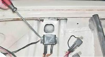
1. Using a Phillips screwdriver, unscrew the two fastening screws and remove the relay. Under one of the screws fixed "mass" the wire.
2. Having marked or remembered the location of the wires, disconnect them from the relay outputs. For convenience, you can sequentially disconnect the wires, immediately connect them to a working relay.
3. Installation of the relay is carried out in the reverse order.
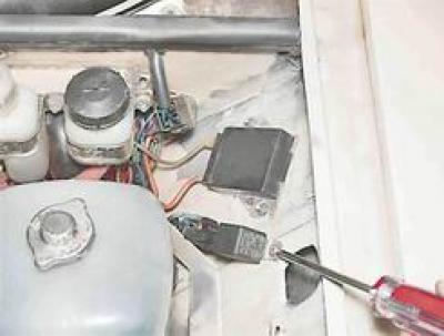
Replacing the relay for turning on the radiator fan of the cooling system (90.3747-10 or 113.3747-10)
The relay for turning on the radiator fan of the cooling system is installed in the engine compartment on the top of the left mudguard.
1. Using a Phillips screwdriver, unscrew the fastening screw and remove the relay.
2. Having marked or remembered the location of the wires, disconnect them from the relay outputs. For convenience, you can sequentially disconnect the wires, immediately connect them to a working relay.
3. Installation of the relay is carried out in the reverse order.