




Examination
To complete the work you will need a multimeter.
1. Remove the generator from the car (see "Generator - removal and installation").
2. Using a rag, clean the outer surface of the generator from dirt.
3. By connecting the positive probe of the ohmmeter to terminal "30" and the negative probe to the generator body, we check the generator diodes for "breakdown".
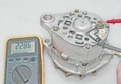
If the ohmmeter shows a resistance close to zero, one or more diodes have broken down or the stator winding has short-circuited to the housing.
4. Connect the positive probe of the ohmmeter to terminal "30" and the negative probe to one of the rectifier block mounting bolts and check the positive diodes.
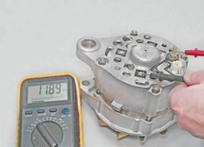
If the ohmmeter shows a resistance close to zero, one or more diodes have broken down.
5. Having connected the positive probe of the ohmmeter to one of the rectifier block mounting bolts, and the negative one to the generator body, we check the negative diodes of the generator for "breakdown".
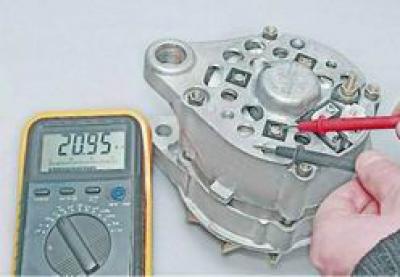
If the ohmmeter shows a resistance close to zero, one or more diodes have broken down.
6. By connecting one probe of the ohmmeter to the terminal "67" of the generator, and the other to the body, we check the reliability of the brushes' fit to the contact rings and the absence of a short circuit in the excitation winding.
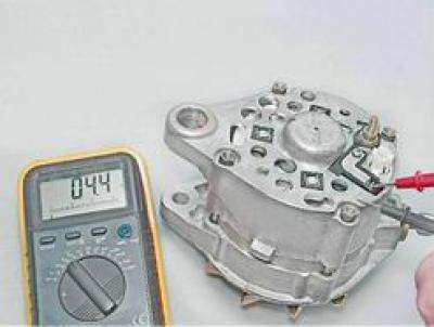
If there are no short-circuited turns in the winding and the brushes are tightly fitted, the resistance should be within 4.2-4.7 Ohms at a temperature of 20°C.
7. Remove the brush holder (see below, "Repair"). When pressing on the brushes, they should move freely in the grooves and be spring-loaded. The protrusion of the brushes from the brush holder in a free state should be at least 5 mm, otherwise the brush holder is replaced.
8. By connecting one ohmmeter probe to the housing and the other to the rotor slip ring, we check for a short circuit between the rotor winding and the generator housing.
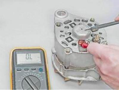
If the ohmmeter shows a resistance close to zero, a short circuit has occurred.
A faulty rotor, stator, capacitor or brush holder must be replaced. If one diode is faulty, replace the rectifier unit as a whole.
Repair
To perform the work you will need: a two- or three-jaw puller, a mandrel for pressing out the front bearing, a mandrel for pressing in the rear bearing.
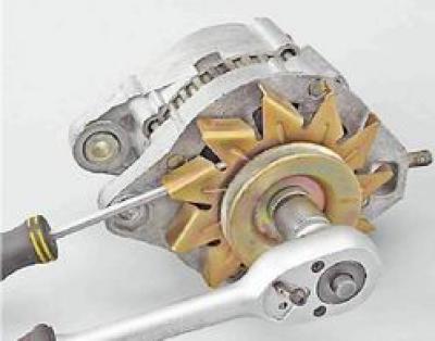
1. Hold the rotor from turning with a screwdriver and use a socket wrench by 19 mm we unscrew the nut securing the pulley and the generator impeller.
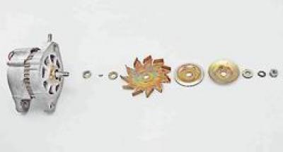
2. Remove the pulley parts, generator cooling impeller, segment key and limit washers from the shaft.
3. Using a Phillips screwdriver, unscrew the brush holder mounting screw.
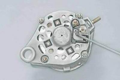
4. Remove the brush holder from the generator housing.
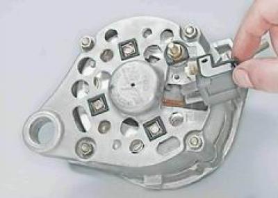
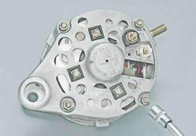
5. With a socket wrench by 10 mm we unscrew the four nuts securing the generator covers and remove the connecting bolts.
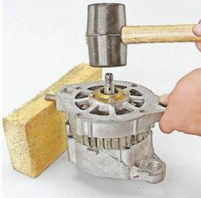
6. Lean the front cover of the generator onto a wooden block and press it off the stator using light blows on the shaft.
7. Remove the generator cover and spacer sleeve.
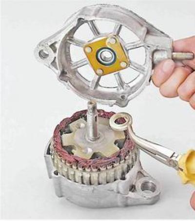
8. Check the technical condition of the front bearing. Holding the cover, rock and turn the inner ring of the bearing in both directions. The bearing rotation should be smooth, the axial play should be insignificant. Replace the faulty bearing.
9. When replacing the front bearing with a socket or open-end wrench by 8 mm unscrew the four nuts. If the nuts do not unscrew, then grind down the punched ends of the bolts.
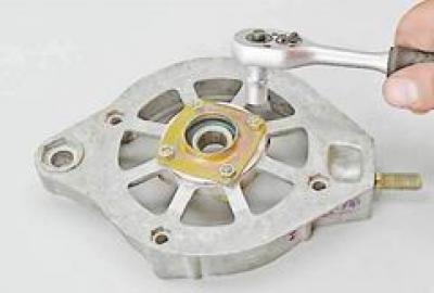
Attention! After installing the bolts and tightening the nuts, the ends of the bolts must be punched. If the length of the bolts is not enough to punch them, then replace the bolts.
10. Remove the bolts and remove the inner and outer bearing mounting washers.
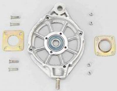
11. Using a mandrel of suitable diameter, press out the bearing.
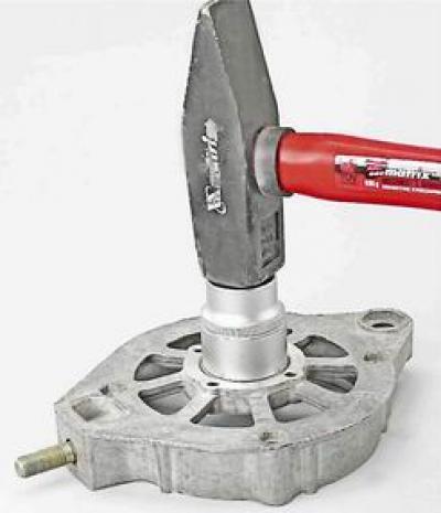
12. Support the edges of the rear cover of the generator (for example, on two wooden blocks), we knock out the rotor using a soft metal punch.
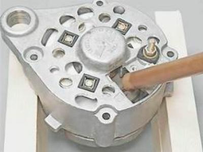
13. Check the technical condition of the rear bearing. The bearing rotation should be smooth, the axial play should be insignificant. There should be no loud noise when the outer ring rotates quickly. Replace the faulty bearing.
14. If it is necessary to replace the bearing, use a puller to press it off the rotor shaft.
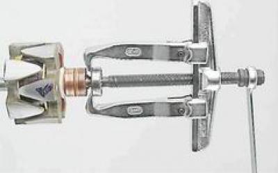
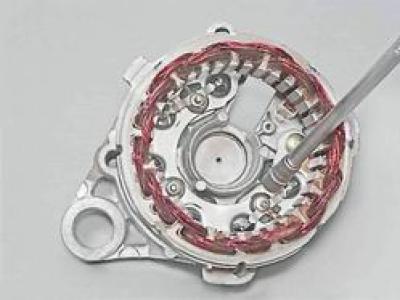
15. With a socket wrench by 8 mm using an extension cord, unscrew the three nuts securing the rectifier block and the stator winding terminals.
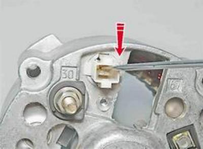
16. Using a thin slotted screwdriver, press the latch of the central terminal of the stator winding and push the terminal into the hole in the block.
17. After removing three bolts, remove the stator from the cover.
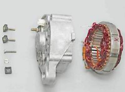
The insulation of the stator winding wires must be free of signs of overheating.
18. With a socket wrench by 10 mm with a deep head, unscrew the terminal nut "30" and remove the insulating washer A.
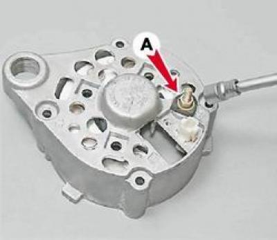
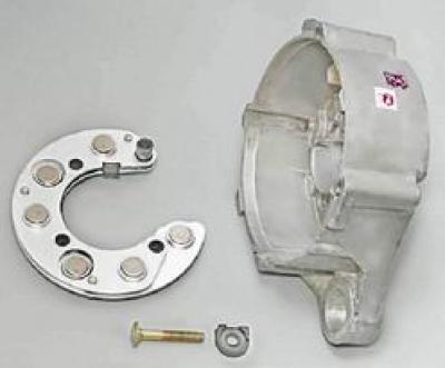
19. Remove the rectifier block.
Assembly
1. Clean the generator parts from dirt and dust, blow with compressed air, metal parts (except bearings) wash with white spirit or kerosene.
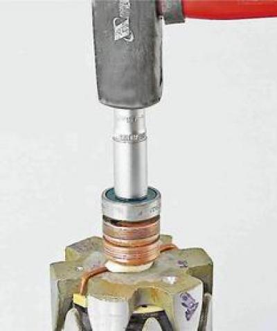
2. Using a mandrel that matches the diameter of the inner ring, press the new bearing onto the rotor axis with light blows.
3. Check the bearing mounting holes in the covers. The holes should not be deformed, there should be no burrs on their surfaces. If necessary, use a file or scraper to restore the chamfer of the hole edges. Replace cracked covers.
4. The misalignment of the holes in the generator cover lugs should be no more than 0.4 mm. When assembling, for the mutual orientation of the covers, use a fastening bolt and a buffer sleeve.
5. The generator is assembled in the reverse order.