English Русский
Български
Беларускі
Український
Српски
Hrvatski
Română
Polski
Slovenský
Magyar
| Articles | Contacts | Sitemap |   
Repair and maintenance Lada Repair and maintenance Mazda Repair and maintenance Mitsubishi Repair and maintenance Toyota Repair and maintenance Land Rover Repair and maintenance Hyundai Repair and maintenance Nissan
VAZbook.ru


Main     1111   2101   2105   2106   2107   2109   2110   2115   2121  
VAZ-2104 (1984-2012) VAZ-2105 (1979-2010) VAZ-21051 (1979-2010)
  • Main
  • «Zhiguli»
  • VAZ-2104
  • Electrical equipment
  • Engine electrics
  • Generator — Checking and Repairing

Generator — Checking and Repairing (VAZ-2104)

            0

Contents: Examination ↓ Repair ↓ Assembly ↓

Examination


To complete the work you will need a multimeter.

1. Remove the generator from the car (see above "Generator - removal and installation").

2. Using a rag, clean the outer surface of the generator from dirt.

3. By connecting the positive probe of the ohmmeter to terminal "30" and the negative probe to the generator body, we check the generator diodes for "breakdown".
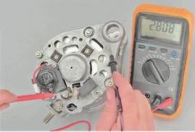
3. By connecting the positive probe of the ohmmeter to terminal «30» and the negative probe to the…


If the ohmmeter shows a resistance close to zero, one or more diodes have broken down or the stator winding has short-circuited to the housing.

4. Connect the positive probe of the ohmmeter to terminal "30" and the negative probe to one of the rectifier block mounting bolts and check the positive diodes.
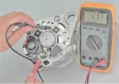
4. Connect the positive probe of the ohmmeter to terminal «30» and the negative probe to one of the…


If the ohmmeter shows a resistance close to zero, one or more diodes have broken down.


5. Having connected the positive probe of the ohmmeter to one of the rectifier block mounting bolts, and the negative one to the generator body, we check the negative diodes of the generator for "breakdown".
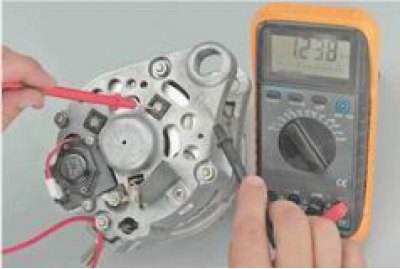
5. Having connected the positive probe of the ohmmeter to one of the rectifier block mounting…


If the ohmmeter shows a resistance close to zero, one or more diodes have broken down.

6. To check the capacitor, remove it from the generator (see "Repair" below). When connecting the ohmmeter probes to the capacitor terminals, the resistance should decrease and then gradually increase.

7. To check the regulator, remove it from the generator (see "Repair" below). When pressing on the brushes, they should move freely in the grooves and be spring-loaded. The protrusion of the brushes in a free state from the brush holder should be at least 5 mm, otherwise replace the regulator.

8. Connect the "B" terminal of the voltage regulator to the positive terminal of the battery, and the negative terminal (shown by arrow A) - with "mass". We measure the voltage on the contacts of the brush assembly with a voltmeter.
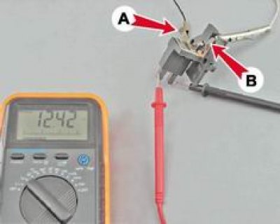
8. Connect the «B» terminal of the voltage regulator to the positive terminal of the battery, and…


If there is no voltage, the regulator is faulty.


9. By connecting one contact of the ohmmeter to the housing and the other to the rotor slip ring, we check for a short circuit between the rotor winding and the generator housing.
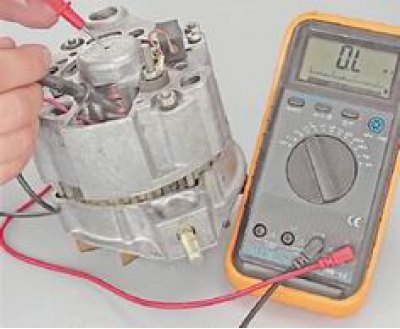
9. By connecting one contact of the ohmmeter to the housing and the other to the rotor slip ring,…


If the ohmmeter shows a resistance close to zero, a short circuit has occurred.

A faulty rotor, stator, capacitor or voltage regulator must be replaced. If one diode is faulty, replace the rectifier unit as a whole.

Repair


To perform the work you will need: a two- or three-jaw puller, a mandrel for pressing out the front bearing, a mandrel for pressing in the rear bearing.

1. Hold the rotor from turning with a screwdriver and use a socket wrench by 19 mm we unscrew the nut securing the pulley and the generator impeller.
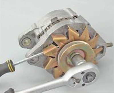
1. Hold the rotor from turning with a screwdriver and use a socket wrench by 19 mm we unscrew the…


2. Remove the pulley parts, generator cooling impeller, segment key and limit washers from the shaft.
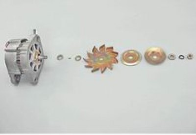
2. Remove the pulley parts, generator cooling impeller, segment key and limit washers from the…


3. To remove the voltage regulator, disconnect the wire connector from it.
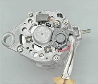
3. To remove the voltage regulator, disconnect the wire connector from it.


4. Using a Phillips screwdriver, unscrew the two screws securing the voltage regulator.
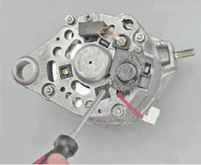
4. Using a Phillips screwdriver, unscrew the two screws securing the voltage regulator.


5. Remove the voltage regulator assembly with the brush unit from the generator housing.
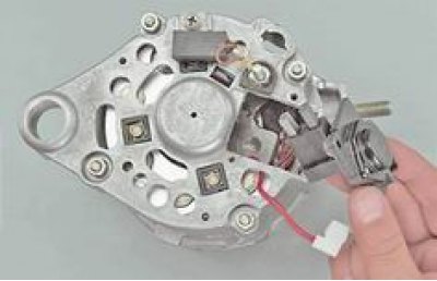
5. Remove the voltage regulator assembly with the brush unit from the generator housing.


6. With a socket wrench by 10 mm we unscrew the four nuts securing the generator covers and remove the connecting bolts.
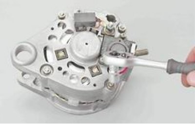
6. With a socket wrench by 10 mm we unscrew the four nuts securing the generator covers and remove…


7. Lean the front cover of the generator onto a wooden block and press it off the stator using light blows on the shaft.
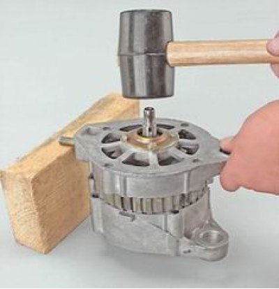
7. Lean the front cover of the generator onto a wooden block and press it off the stator using…


8. Remove the generator cover and spacer sleeve.
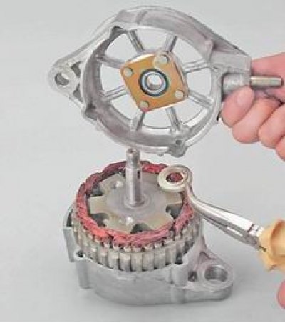
8. Remove the generator cover and spacer sleeve.


9. Check the technical condition of the front bearing. Holding the cover, rock and turn the inner ring of the bearing in both directions. The bearing rotation should be smooth, the axial play should be insignificant. Replace the faulty bearing.

10. When replacing the front bearing with a socket or open-end wrench by 8 mm unscrew the four nuts. If the nuts do not unscrew, then grind down the punched ends of the bolts.
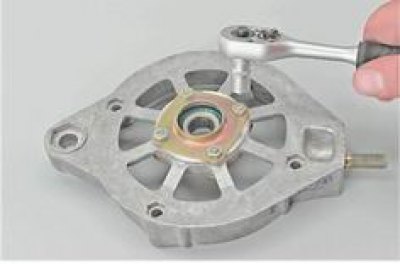
10. When replacing the front bearing with a socket or open-end wrench by 8 mm unscrew the four…


Attention! After installing the bolts and tightening the nuts, the ends of the bolts must be punched. If the length of the bolts is not enough to punch them, then replace the bolts with new ones.


11. Remove the bolts and remove the inner and outer bearing mounting washers.
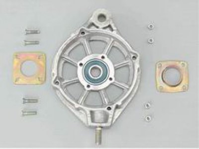
11. Remove the bolts and remove the inner and outer bearing mounting washers.


12. Using a mandrel of suitable diameter, press out the bearing.
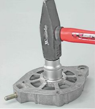
12. Using a mandrel of suitable diameter, press out the bearing.


13. Support the edges of the rear cover of the generator (for example, on two wooden blocks), we knock out the rotor using a soft metal punch.
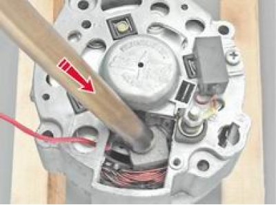
13. Support the edges of the rear cover of the generator (for example, on two wooden blocks), we…


14. Check the technical condition of the rear bearing. The bearing should roll smoothly, the axial play should be insignificant. There should be no loud noise when the outer ring rotates quickly. Replace the faulty bearing.

15. If it is necessary to replace the bearing, use a puller to press it off the rotor shaft.
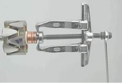
15. If it is necessary to replace the bearing, use a puller to press it off the rotor shaft.


16. With a socket wrench by 8 mm using an extension cord, unscrew the three nuts securing the rectifier block and the stator winding terminals.
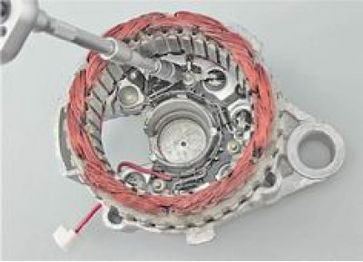
16. With a socket wrench by 8 mm using an extension cord, unscrew the three nuts securing the…


17. After removing two bolts, remove the stator from the cover.
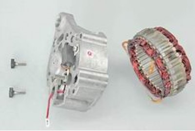
17. After removing two bolts, remove the stator from the cover.


The insulation of the stator winding wires must be free of signs of overheating.

18. With a socket wrench by 10 mm using a deep head, unscrew the terminal nut "30" and remove the insulating washer A.
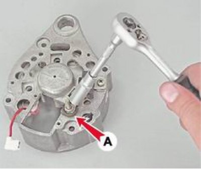
18. With a socket wrench by 10 mm using a deep head, unscrew the terminal nut «30» and remove the…


19. Remove the rectifier block.

19. Remove the rectifier block.


20. Using a Phillips screwdriver, unscrew the screw securing the capacitor and remove it. Remove the third bolt B securing the rectifier unit from the hole in the cover.
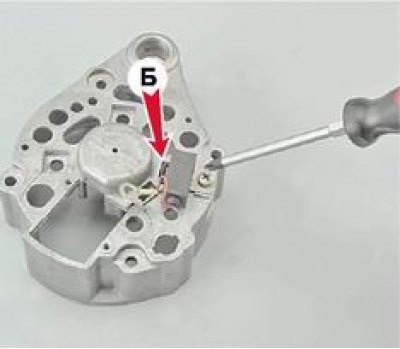
20. Using a Phillips screwdriver, unscrew the screw securing the capacitor and remove it. Remove…


Assembly


1. Clean the generator parts from dirt and dust, blow with compressed air, metal parts (except bearings) wash with white spirit or kerosene.

2. Using a mandrel that matches the diameter of the inner ring, press the new bearing onto the rotor axis with light blows.
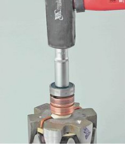
2. Using a mandrel that matches the diameter of the inner ring, press the new bearing onto the…


3. Check the bearing mounting holes in the covers. The holes should not be deformed, there should be no burrs on their surfaces. If necessary, use a file or scraper to restore the chamfer of the hole edges. Replace cracked covers.

4. The misalignment of the holes in the generator cover lugs should be no more than 0.4 mm. When assembling, for the mutual orientation of the covers, use a fastening bolt and a buffer sleeve.

5. The generator is assembled in the reverse order.


This article is available at russian, bulgarian, belarusian, ukrainian, serbian, croatian, romanian, polish, slovak, hungarian
The text was reviewed by the specialist: Grigory Vologodtsev

Share with friends:

Previous articles
VAZ-2104: Engine electrics
Next articles

Generator — removal and installation
Generator Drive Belt — Tension Adjustment and Replacement
Description of the generator design
Battery — Removal and Installation
Battery pack — Maintenance
Description of the starter design
Starter — removal and installation
Starter — check and repair
Spark plugs — checking condition and replacement
Ignition switch (lock) — removal, inspection and replacement of the contact group

More articles from other manuals on VAZ cars:
➠ Generator — Checking and Repairing VAZ-2106 (1976-2006)
➠ Generator — Checking and Repairing VAZ-2107 (1982-2012)
➠ Checking and repairing the coolant pump VAZ-1111 (1988-1996)
➠ Checking and repairing the brake pedal assembly VAZ-2101 (1970-1983)
➠ Electric Fan — Checking and Repairing VAZ-2108 (1984-2003)
Link in different formats to this page


Visitor comments

No comments yet


How much will 42 + 19 ?


VAZ-2104 (1984-2012) 
  • General information
  • Operation and maintenance
  • Power unit
  • Engine repair
  • Fuel system (carburetor)
  • Fuel system (injector)
  • Control system
  • Cooling system
  • Exhaust system
  • Transmission
  • Clutch
  • Car gearbox
  • Cardan gear
  • Rear axle
  • Chassis
  • Front suspension
  • Rear suspension
  • Wheels and tires
  • Steering
  • Brake system
  • Body
  • Exterior
  • Interior
  • Doors and glass
  • Ventilation and heating
  • Electrical equipment
  • Equipment and devices
  • Headlights and lighting
  • Engine electrics
  • Electrical circuits


VAZ-2105 (1979-2010) 
  • General information
  • Vehicle description
  • Vehicle device
  • Vehicle operation
  • Maintenance
  • Power unit
  • Engine repair
  • Cooling and lubrication system
  • Supply system
  • Transmission
  • Clutch
  • Car gearbox
  • Cardan gear
  • Rear axle
  • Chassis
  • Suspension and shock absorbers
  • Steering
  • Brake system
  • Body
  • Body elements
  • Electrical equipment
  • Engine electrics
  • Equipment and devices


VAZ-21051 (1979-2010) 
  • General information
  • Introduction to guide
  • User manual
  • Troubleshooting
  • Power unit
  • Engine repair
  • Engine repair VAZ-2103
  • Cooling system
  • Lubrication system
  • Power and exhaust system
  • Fuel injection
  • Transmission
  • Clutch
  • Car gearbox
  • Cardan gear
  • Rear axle
  • Chassis
  • Suspension and shock absorbers
  • Steering
  • Brake system
  • Body
  • Exterior
  • Interior
  • Doors and windows
  • Electrical equipment
  • Equipment and devices
  • Engine electrics
  • Ignition system
  • Electrical circuits


VAZbook.ru © 2017 · Mobile version · Contact with administration · Sitemap: EN BG BY UA RS HR RO PL SK HU · Site search · News and articles VAZ-1111 · VAZ-11113 · VAZ-2101 · VAZ-21011 · VAZ-2104 · VAZ-2105 · VAZ-21051 · VAZ-2106 · VAZ-21061 · VAZ-2107 · VAZ-21099 · VAZ-2109 · VAZ-2108 · VAZ-2110 · VAZ-2112 · VAZ-2114 · VAZ-2115 · VAZ-2121 · VAZ-21213 · VAZ-21214 ·
The site stores technical data using cookies to improve the service.