
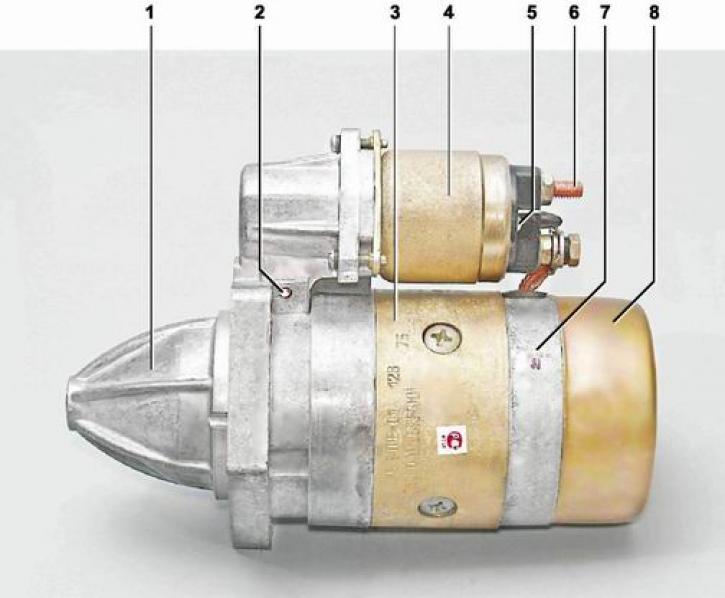
Starter 35.3708: 1 - front cover; 2 - axis of the drive lever; 3 - body; 4 - starter traction relay; 5 - output "50" traction relay; 6 - contact bolt; 7 - back cover of the starter; 8 - casing
The starter is a four-brush, four-pole mixed-excitation DC motor. It is installed on the right side of the cylinder block and is attached with three bolts to the clutch housing.
Technical characteristics of starter 35.3708:
|
Rated voltage, V |
12 |
|
Rated power, kW |
1,3 |
|
Starting current in the inhibited state, A |
550 |
|
Idle current, A |
60 |
|
Direction of rotation |
right |
|
Working mode |
short-term with a duration of not more than 10 s |
The starter consists of a housing with excitation windings, an armature with a drive gear and an overrunning clutch, two covers and a traction electromagnetic relay. The covers and the starter housing are pulled together with two bolts.
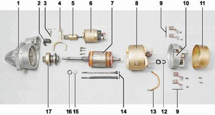
Starter details 35.3708: 1 - front cover; 2 - sealant; 3 - axis of the drive lever; 4 - drive lever; 5 - stock; 6 - starter traction relay; 7 - anchor; 8 - housing with a stator; 9 - brushes; 10 - back cover of the starter; 11 - casing; 12 - lock washer; 13 - jumper; 14 - coupling bolts; 15 - retaining ring; 16 - restrictive ring of the gear stroke; 17 - overrunning clutch with drive gear
Four poles with excitation windings mounted on them are fixed with screws inside the case. The armature shaft rotates in two bronze-graphite bushings pressed into the starter covers. The armature consists of a shaft, a core with a winding and a collector. At the front end of the shaft, a drive gear is movably mounted, rigidly connected to the hub of the overrunning roller clutch. The movement of the gear on the shaft is limited by the ring. On the inner surface of the hub, screw splines are made, which engage with the screw splines of the shaft. A driving ring is installed on the hub, the ears of which fit into the grooves of the drive lever. The other end of the lever rests on the rod of an electromagnetic traction relay, fixed to the front cover with three screws.
In the back cover there is a brush holder with two insulated from the body (positive) and two closed to the body (negative) brushes.
Traction relay starter is used to engage the starter drive gear with the flywheel ring and to close the power circuit of the armature and stator windings. Contact bolts are installed in the relay cover. One bolt is connected by wire to the positive battery terminal, and the other to the stator and relay windings. When the ignition key is turned to position II ("starter"), voltage is applied to the output "50" traction relay covers. In this case, the resulting magnetic field draws the armature. The contact plate closes the contact bolts, and the rod acts on the drive lever. The lever, moving the drive gear, engages it with the ring gear of the engine flywheel. The stator and armature supply current flows through the closed relay contacts. As a result of the interaction of magnetic fields, the starter armature begins to rotate along with the hub and the outer ring of the overrunning clutch. In this case, the overrunning clutch rollers are wedged between the outer and inner rings of the clutch. Torque from the armature shaft is transmitted through the clutch and drive gear to the flywheel crown. After starting the engine, the speed of the gear begins to exceed the speed of the starter armature shaft. The clutch rollers are wedged, while the torque from the flywheel is not transmitted to the starter armature shaft. When the key is returned to position I ("ignition") the power supply circuit of the windings of the traction relay opens and, under the action of the return spring of the relay, the armature returns to its original position, opening the contact bolts and disengaging the drive gear.