




Open large image in new tab »
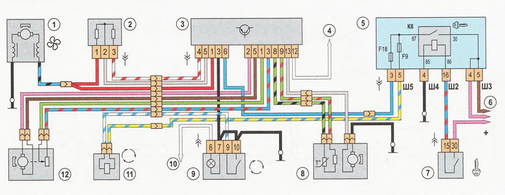
Automatic heater control system diagram: 1 - fan electric motor; 2 - additional resistance; 3 - control unit; 4 - to the switch of lighting and headlights; 5 - mounting block; 6 - to power sources; 7 - ignition switch; 8 - cabin air temperature sensor; 9 - recirculation mode switch; 10 - to the central light switch (side light); 11 - recirculation valve; 12 - damper drive motor-reducer