




View of the headlight from the engine compartment
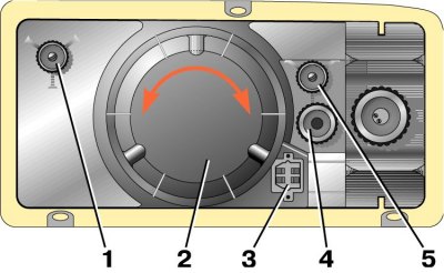
1 – screw for adjusting the light beam in the horizontal direction; 2 – headlight housing; 3 – plug socket; 4 – Set screw; 5 – screw for adjusting the light beam in the vertical direction
Headlight adjustment diagram
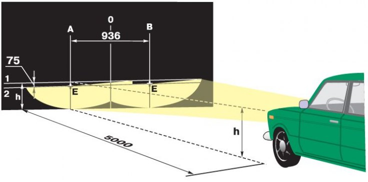
The direction of the headlight beams should be such that the road in front of the car is well lit and oncoming drivers are not blinded when the low beams are turned on.
1. The headlights are adjusted by turning screws 1 and 5 (see Fig. View of the headlight from the engine compartment), which rotate the optical element in vertical and horizontal planes. The most convenient way to adjust the headlights is with the help of movable optical devices. If there are none, then the adjustment can be done using the screen.
2. Place a fully fueled and equipped vehicle with a load of 735 N (75 kgf) on the driver's seat on a flat horizontal surface 5 m from a smooth wall or any screen (plywood shield measuring about 2x1 m, etc.) so that the axis of the car is perpendicular to it.
3. Before marking the screen, make sure the tire pressure is correct, then rock the car from side to side to settle the suspension springs.
The original can be seen on the website www.VAZbook.ru
4. Draw on the screen (see fig. Headlight adjustment diagram) vertical lines: axial 0 and lines A and B passing through points E corresponding to the centers of the headlights. These lines must be symmetrical relative to the axial line of the car. At a height n corresponding to the distance of the centers of the headlights from the floor, draw line 1 and below it 75 mm line 2 of the centers of the light spots.
5. Set the headlight range control knob on the instrument panel to the position corresponding to the vehicle load by one driver. If the vehicle does not have a headlight range control, turn the adjusting screws (see Fig. View of the headlight from the engine compartment) inserted into the headlights instead of the hydraulic corrector working cylinders in the extreme left position.
6. Turn on the low beam headlights.
7. Sequentially, first for the right headlight (the left one is covered with a piece of cardboard or dark material or turned off), and then for the left (the right one is closed) adjust the headlight beams with screws 1 and 5.
8. For adjusted headlights, the upper border of the light spots should coincide with line 2 (see fig. Headlight adjustment diagram), and the points of intersection of the horizontal and inclined sections of the light spots - with points E.