




Engine Crankcase Ventilation Diagram
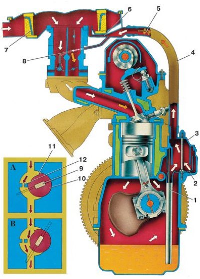
A and B – operation of the carburetor spool valve at low crankshaft speed (A) and at high speed (B);
1 – oil separator drain pipe; 2 – oil separator; 3 – breather cap; 4 – gas suction hose; 5 – flame arrester; 6 – exhaust manifold; 7 – air filter element; 8 – hose for removing gases into the carburetor's throttle space; 9 – primary chamber throttle valve axis; 10 – spool; 11 – spool groove; 12 – calibrated hole
To flush, disconnect ventilation hoses 4 and 8 from the pipes, remove flame arrester 5 from hose 4, remove breather cover 3 and flush them with gasoline or kerosene.
It is also necessary to flush the carburetor valve device, the cavities and pipes of the air filter through which the exhaust gases pass.