
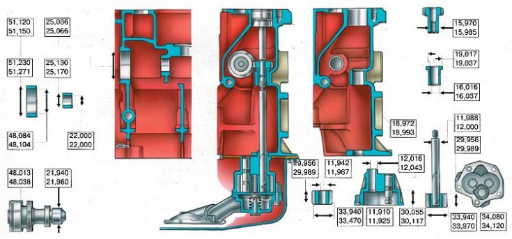
The main dimensions of the oil pump and its drive
Removal and installation
1. Put the car on an inspection ditch or lift, disconnect the wires from the battery and drain the oil from the engine crankcase.
2. Remove the engine mudguard.
3. Loosen the nuts securing the front engine mount pads to the cross member, and slightly raise the engine with a jack or hoist to allow the pad studs to come out of the cross member holes.
4. Remove the crankcase.
5. Remove the oil pump along with the intake pipe.
6. Install the oil pump on the engine in the reverse order of removal.
Oil pump disassembly
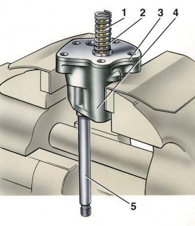
1 - pressure reducing valve; 2 - spring; 3 - cover; 4 - body; 5 - roller
Disassembly and assembly
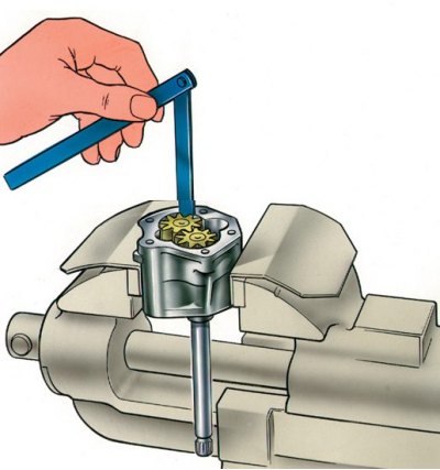
1. Secure the oil pump in a vise, being careful not to damage the housing.
2. Loosen the bolts and remove the intake pipe together with the oil pressure reducing valve.
3. Remove cover 3 of the pump housing and remove the pump shaft with the drive gear and the driven gear from the housing.
4. To assemble, secure the pump carefully in a vise.
5. Install the drive gear with the shaft into the pump housing, and put the driven gear on the axle in the housing.
6. Install the housing cover, pressure reducing valve with spring and attach the suction pipe to the pump housing.
Attention! After assembling the pump, when turning the drive shaft by hand, the gears should rotate smoothly and without jamming.
Checking pump parts
1. After dismantling, wash all pump parts with kerosene or gasoline, blow with compressed air, and then inspect the pump housing and cover; Replace parts if cracked.
2. Check with a set of feelers the gaps between the teeth of the gears, as well as between the outer diameters of the gears and the walls of the pump housing, which should be 0.15 mm, respectively (maximum allowable 0.25 mm) and 0.11–0.18 mm (maximum allowable 0.25 mm).
3. If the clearances exceed the limits, then replace the gears, and if necessary, the pump housing.
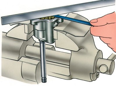
4. Using a feeler gauge and a ruler, check the gap between the ends of the gears and the plane of the housing, which should be equal to 0.066–0.161 mm (maximum allowable 0.2 mm). If the clearance is greater than 0.2 mm, replace the gears or pump housing, whichever is worn.
5. Check the clearance between the driven gear and its axle, which should be 0.017–0.057 (maximum allowable 0.1 mm), as well as between the pump shaft and the hole in the housing, this gap should be 0.016–0.055 (maximum allowable 0.1 mm). If the clearances are out of range, replace the worn parts.
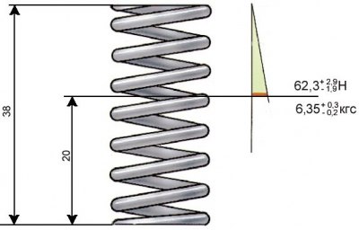
Basic data for checking the pressure reducing valve spring
Checking the pressure reducing valve
When repairing the oil pump, check the pressure reducing valve. Pay attention to the surfaces of the valve and body, as possible contamination or deposits on the mating surfaces can cause seizing. The mating surface of the valve must be free of nicks and burrs that could reduce system pressure.
Check the elasticity of the pressure reducing valve spring by comparing the obtained data with those shown in the figure.