




It is also necessary to flush the carburetor valve device, the cavities and pipes of the air filter through which the exhaust gases pass.
Since 1987, hose 8 for removing crankcase gases into the carburetor's throttle space has been extended to oil separator 2.
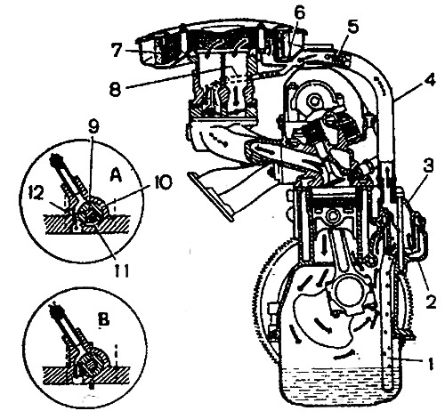
Fig. 2-75. Diagram of the engine crankcase ventilation system: A and B - operation of the carburetor spool valve at low crankshaft speed (A) and at high speed (B): 1 - oil separator drain pipe; 2 - water separator; 3 - breather cap; 4 - gas extraction hose, 5 - flame arrester; 6 - exhaust manifold; 7 - air filter element; 8 - hose for removing gases into the carburetor's throttle space; 9 - primary chamber throttle valve axis; 10 - spool, 11 - spool groove; 12 - calibrated hole
(The text is copied from the online portal: «VAZBOOK.ru»)