




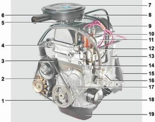
Engine: 1 - crankshaft pulley; 2 - generator; 3 - coolant pump; 4 - thermostat; 5 - carburetor; 6 - air intake; 7 - air filter housing; 8 - oil filler cap; 9 - cylinder head cover; 10 - ignition distributor; 11 - cylinder head; 12 - coolant temperature gauge sensor; 13 - cylinder block; 14 - oil separator of the crankcase ventilation system; 15 - flywheel; 16 - fuel pump; 17 - camshaft drive cover; 18 - oil filter; 19 - Engine oil pan
Depending on the modification, one of three engines can be installed on the car: 2106 (volume 1.6 l), 2103 (volume 1.5 l) or 21011 (volume 1.3 l).
Engine - carburetor, petrol, four-stroke, four-cylinder, in-line, eight-valve, with overhead camshaft.
The 2106 engine is based on the 2103 engine and has a larger cylinder diameter, so the pistons and rings are not interchangeable. The timing drive parts and crankshafts of these engines are identical.
The 21011 engine has the same cylinder diameter as the 2106, but has a shorter piston stroke.
Cylinder block cast from high-strength cast iron. The engine cylinders are bored in the block and honed. According to diameter, the cylinders are divided into 5 classes through 0.01 mm and are marked on the lower plane of the block with the letters A, B, C, D and E. The cylinders are arranged vertically in one row.
Crankshaft, cast from high-strength cast iron, mounted in the lower part of the block on five support journals. The shaft rotates in steel-aluminum liners, on the steel base of which a layer of aluminum-tin alloy is applied. The holes for the main bearings are machined together with the bearing caps, therefore the caps are not interchangeable. On the outer surfaces of the main bearing caps there are marks corresponding to their serial number (counting from the front end of the crankshaft). To prevent axial movement of the crankshaft, two thrust half rings are installed in the grooves of its rear support - steel-aluminum and metal-ceramic. The front crankshaft oil seal is installed in the camshaft drive cover, "working" on the outer surface of the pulley. The rear oil seal is pressed into the holder, attached to the cylinder block, and "works" on the surface of the crankshaft flange. The front bearing of the primary shaft of the gearbox is pressed into the rear end of the crankshaft.
Connecting rod - steel, forged. The lower head of the connecting rod is detachable, and connecting rod liners are installed in it. The hole in the lower head of the connecting rod is machined together with the cover, so the covers are not interchangeable. In order not to mix up the connecting rod covers, the numbers of the cylinders in which they are installed are applied on the sides of the connecting rods and covers.
A piston pin is pressed into the upper head of the connecting rod and rotates freely in the piston bosses.
Pistons are cast from aluminum alloy, and their outer surface (to improve the adhesion to the cylinder walls) covered with a layer of tin. Piston skirt (to compensate for uneven thermal expansion) has a complex geometric shape: it is conical in height and oval in cross-section. Therefore, the piston diameter should be measured in a plane perpendicular to the piston pin, at a distance of 52.4 mm from the piston bottom. The axis of the hole for the piston pin is shifted to the right of the piston symmetry axis. Piston rings made of special cast iron are installed in the piston grooves. Closer to the piston bottom there are two compression rings, and one oil scraper ring is located near the skirt. The upper compression ring has a convex working surface covered with porous chrome, and the lower one is phosphated, scraper type. The oil scraper ring is two-component: it consists of a ring and an expander. The working surface of the ring is chrome-plated.
Cylinder head is cast from an aluminum alloy and is attached to the block with eleven bolts. A non-shrink gasket is installed between the head and the block. The seats and valve guides, made of cast iron, are pressed into the block head. Oil-deflecting caps are pressed onto the valve guides on top, which are necessary to reduce the flow of oil into the combustion chamber through the gaps between the stem and the guide sleeve. The valves are made of heat-resistant steel and are driven (through levers) camshaft rotating in an aluminum bearing housing.
Camshaft - five-support, eight-cam, cast iron. The shaft is held from axial movement by a support flange. A driven sprocket is installed on the front end of the shaft. The camshaft and auxiliary unit shaft are driven from the leading sprocket of the crankshaft by a double-row roller chain. The drive is equipped with a damper and a chain tensioner with a shoe.
Flywheel is mounted on the rear end of the crankshaft and is attached to it with six bolts. The flywheel is cast iron, with a pressed-on toothed ring, which is necessary for starting the engine with a starter. When assembling a new engine, the flywheel is balanced together with the crankshaft.