English Русский
Български
Беларускі
Український
Српски
Hrvatski
Română
Polski
Slovenský
Magyar
| Articles | Contacts | Sitemap |   
Repair and maintenance Lada Repair and maintenance Mazda Repair and maintenance Mitsubishi Repair and maintenance Toyota Repair and maintenance Land Rover Repair and maintenance Hyundai Repair and maintenance Nissan
VAZbook.ru


Main     1111   2101   2105   2106   2107   2109   2110   2115   2121  
VAZ-2104 (1984-2012) VAZ-2105 (1979-2010) VAZ-21051 (1979-2010)
  • Main
  • «Zhiguli»
  • VAZ-2104
  • Power unit
  • Engine repair
  • Camshaft and valve levers — replacement

Camshaft and valve levers — replacement (VAZ-2104)

            0

Contents: Removal ↓ Installation ↓
The work is shown on the example of a carburetor engine. On an injection engine the work is performed similarly.

To complete the work you will need a torque wrench.

Removal


1. Prepare the vehicle for operations (see "Preparing a car for maintenance and repair").

2. Remove the cylinder head cover (see "Cylinder Head Cover Gasket - Replacement").

3. Set the camshaft to the position corresponding to the end of the compression stroke in the 4th cylinder (see "Clearance between valve levers and camshaft cams - adjustment").

4. Using a chisel, bend back the tab of the lock washer on the camshaft sprocket mounting bolt.
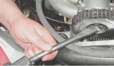
4. Using a chisel, bend back the tab of the lock washer on the camshaft sprocket mounting bolt.


5. Engage first gear. Using a socket wrench by 17 mm we unscrew the bolt and remove it together with the washers.
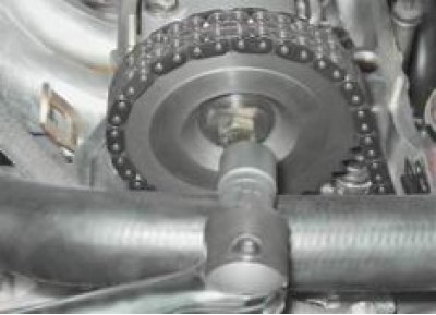
5. Engage first gear. Using a socket wrench by 17 mm we unscrew the bolt and remove it together…


6. Remove the chain tensioner (see "Timing Chain Tensioner - Replacement").


7. Remove the sprocket with the chain. To prevent the chain from jumping, tie it with wire to the sprocket and place it in the cylinder head.
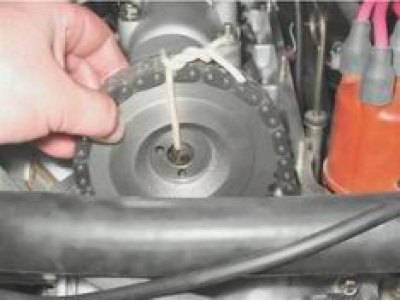
7. Remove the sprocket with the chain. To prevent the chain from jumping, tie it with wire to the…


8. With a socket wrench by 13 mm evenly unscrew the nine nuts securing the camshaft bearing housing.
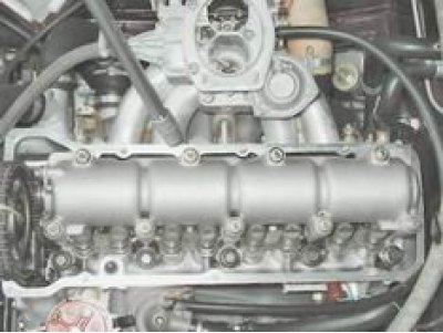
8. With a socket wrench by 13 mm evenly unscrew the nine nuts securing the camshaft bearing housing.


9. Remove the housing assembly with the camshaft from the cylinder head studs.
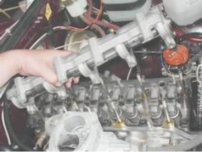
9. Remove the housing assembly with the camshaft from the cylinder head studs.


10. With a socket or open-end wrench by 10 mm we unscrew the two bolts securing the thrust flange to the bearing housing and remove the flange from the groove in the front support journal of the shaft.
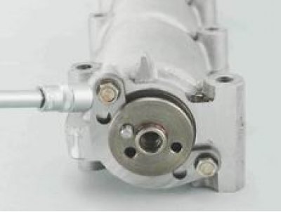

10. With a socket or open-end wrench by 10 mm we unscrew the two bolts securing the thrust flange…


11. Remove the camshaft from the bearing housing.
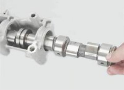
11. Remove the camshaft from the bearing housing.


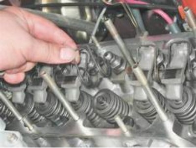
12. After lifting the valve lever and releasing it from the spring, remove the lever from the adjusting bolt.
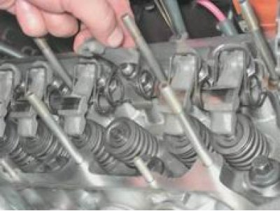
12. After lifting the valve lever and releasing it from the spring, remove the lever from the…


13. Remove the lever spring.

13. Remove the lever spring.


We remove the remaining levers and springs in the same way.

14. Inspect the working surfaces of the cams and journals of the camshaft, the bearing housing, and the levers. If the cams are worn by more than 0.5 mm, or if there are nicks or gouges, the camshaft must be replaced. Cracks on the housing surface are not allowed. No nicks or scratches are allowed on the working surfaces of the journal supports. The working surfaces of the levers must also be free of nicks and signs of severe wear.

Installation


1. Before installing the camshaft into the bearing housing, lubricate the working surfaces of the cams and journals with engine oil.

(View the original on the internet resource: «www.vazbook.ru»)

2. Install the camshaft into the housing and secure the shaft with a thrust flange. Orient the camshaft so that its pin is opposite the upper hole in the thrust flange.
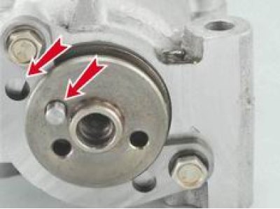
2. Install the camshaft into the housing and secure the shaft with a thrust flange. Orient the…


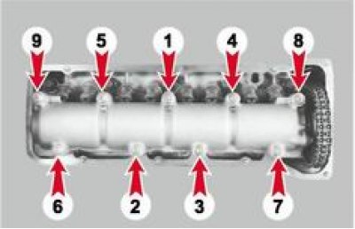
3. Tighten the bearing housing mounting nuts in the order shown in the photo, to a torque of 18.3-22.6 N·m.

3. Tighten the bearing housing mounting nuts in the order shown in the photo, to a torque of…


4. Untie the wire, install the sprocket with the chain on the camshaft, tighten the mounting bolt and lock it by bending the petals of the lock washer.

5. Install the chain tensioner (see "Timing Chain Tensioner - Replacement").

6. Adjust the clearance between the valve levers and the camshaft cams (see "Clearance between valve levers and camshaft cams - adjustment").

7. Installation of all removed parts is carried out in reverse order.


This article is available at russian, bulgarian, belarusian, ukrainian, serbian, croatian, romanian, polish, slovak, hungarian
The text was reviewed by the specialist: Grigory Vologodtsev

Share with friends:

Previous articles
VAZ-2104: Engine repair
Next articles

Timing Chain Tensioner — Replacement
Gas distribution mechanism drive chain-replacement
Gas distribution mechanism drive chain-tension adjustment
Cylinder Head Cover Gasket — Replacement
Clearance between valve levers and camshaft cams — adjustment
Valve timing oil seals — replacement
Oil Pressure Sensor — Replacement
Engine oil pan — removal and installation
Oil Pump Drive Gear — Replacement

More articles from other manuals on VAZ cars:
➠ Camshaft and valve levers — replacement VAZ-2106 (1976-2006)
➠ Camshaft and valve levers — replacement VAZ-2107 (1982-2012)
➠ Removal the camshaft and valve drive levers of the injection… VAZ-21214 (1994-2006)
➠ Valve Levers — Checking VAZ-21011 (1974-1983)
➠ Adjusting the tension of the camshaft drive belt VAZ-1111 (1988-1996)
Link in different formats to this page


Visitor comments

No comments yet


How much will 41 + 22 ?


VAZ-2104 (1984-2012) 
  • General information
  • Operation and maintenance
  • Power unit
  • Engine repair
  • Fuel system (carburetor)
  • Fuel system (injector)
  • Control system
  • Cooling system
  • Exhaust system
  • Transmission
  • Clutch
  • Car gearbox
  • Cardan gear
  • Rear axle
  • Chassis
  • Front suspension
  • Rear suspension
  • Wheels and tires
  • Steering
  • Brake system
  • Body
  • Exterior
  • Interior
  • Doors and glass
  • Ventilation and heating
  • Electrical equipment
  • Equipment and devices
  • Headlights and lighting
  • Engine electrics
  • Electrical circuits


VAZ-2105 (1979-2010) 
  • General information
  • Vehicle description
  • Vehicle device
  • Vehicle operation
  • Maintenance
  • Power unit
  • Engine repair
  • Cooling and lubrication system
  • Supply system
  • Transmission
  • Clutch
  • Car gearbox
  • Cardan gear
  • Rear axle
  • Chassis
  • Suspension and shock absorbers
  • Steering
  • Brake system
  • Body
  • Body elements
  • Electrical equipment
  • Engine electrics
  • Equipment and devices


VAZ-21051 (1979-2010) 
  • General information
  • Introduction to guide
  • User manual
  • Troubleshooting
  • Power unit
  • Engine repair
  • Engine repair VAZ-2103
  • Cooling system
  • Lubrication system
  • Power and exhaust system
  • Fuel injection
  • Transmission
  • Clutch
  • Car gearbox
  • Cardan gear
  • Rear axle
  • Chassis
  • Suspension and shock absorbers
  • Steering
  • Brake system
  • Body
  • Exterior
  • Interior
  • Doors and windows
  • Electrical equipment
  • Equipment and devices
  • Engine electrics
  • Ignition system
  • Electrical circuits


VAZbook.ru © 2017 · Mobile version · Contact with administration · Sitemap: EN BG BY UA RS HR RO PL SK HU · Site search · News and articles VAZ-1111 · VAZ-11113 · VAZ-2101 · VAZ-21011 · VAZ-2104 · VAZ-2105 · VAZ-21051 · VAZ-2106 · VAZ-21061 · VAZ-2107 · VAZ-21099 · VAZ-2109 · VAZ-2108 · VAZ-2110 · VAZ-2112 · VAZ-2114 · VAZ-2115 · VAZ-2121 · VAZ-21213 · VAZ-21214 ·
The site stores technical data using cookies to improve the service.