




2. The deformation of the bridge beam is checked in both horizontal and vertical planes.
3. Having attached flange A.70172 to each end of the beam, install the flange beam on identical prisms located on a test plate at least 1600 mm long so that the surface of the crankcase mating to the beam is in a vertical plane.
 |
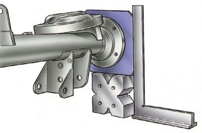 |
4. Check the deformation of the beam by placing a square against the outside (drawing on the left) and side (drawing on the right) flange surfaces A.70172; if the beam is not deformed, the square will fit tightly.
5. The amount of deformation is checked with a feeler gauge. If the 0.2 mm feeler gauge passes through any flange, the beam must be straightened.
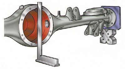
6. Use a square to check the perpendicularity of the gearbox mounting surface relative to the support surface of flange A.70172. A 0.2 mm feeler gauge should not fit.
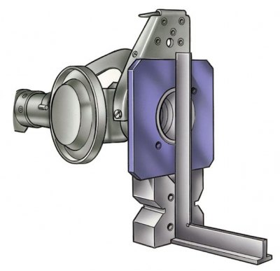
7. Rotate the bridge beam by 900 and install it on the prisms. The square applied to the outer surface of the flange should fit tightly, otherwise check the deformation value with a feeler gauge. A 0.2 mm feeler gauge should not pass.
8. If the deformation exceeds the specified value, straighten the beam following the instructions (see subsection 5.4.5).
9. After all adjustments have been made, thoroughly wash the beam, clean the magnetic plug, install it in place and check the quality of the welds and the tightness of the beam and the cleanliness inside the beam (absence of burrs, chips and oil residues) and the cleanliness of the beam breather.
10. After this, paint the beam from the outside to protect it from corrosion.