




Rear axle beam straightening diagram
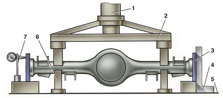
1 – hydraulic cylinder; 2 – pressure crossbar; 3 – flange A.70172; 4 - square; 5 – press table; 6 – emphasis; 7 – indicator stand
1. Attach flanges A.70172 to each end of the beam (used for straightening, not for checking beams) and install it on the supports of the hydraulic press so that the ends of the clamping crossbar 2 are in the deformation zone of the beam. The most probable location of the deformation zone is at a distance of 200–300 mm from the ends of the beam flanges.
2. Install the stand 7 with the indicator so that the indicator leg rests against the upper part of the side surface of the flange, and the indicator pointer is on the division equal to the value of the beam deformation measured with the feeler gauge when checking the beam. On the other side of the beam, install either the stand with the indicator or the square 4.
3. Installed under the beam (in the deformation zone) limit stops 6, straighten the beam with a hydraulic press sequentially in the horizontal and vertical planes, monitoring the results of straightening with an indicator or a feeler gauge on a square 4.
4. The maximum force of the press when straightening the beam should not exceed 98,000 N (10,000 kgf), to prevent excessive deformation of the casing cross-section.
Attention! With a stop height of 6, selected empirically, the beam can be adjusted without checking with a square or indicator.
5. Remove the beam from the press and check it as described above, replacing the A.70172 flanges with "test" ones.
6. In the absence of appropriate equipment, as an exception, it is permissible to straighten the rear axle beam sequentially from each side, but with mandatory checking of the beam deformation on both sides (see subsection 5.4.4).