




The car can be equipped with a five- or four-speed gearbox. Gearbox assemblies and most of their parts are interchangeable.
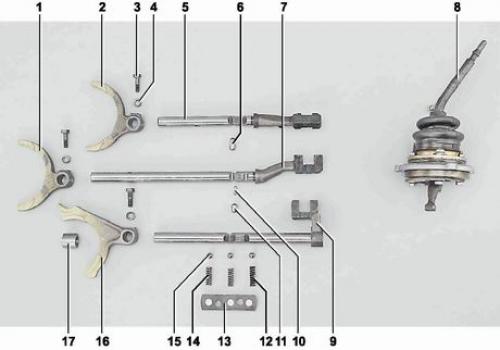
Gear shift drive parts: 1 - fork for engaging III and IV gears (2101-1702024); 2 - fork for engaging 1st and 2nd gears (2101-1702024); 3 - fork mounting bolt (2101-1702028); 4 - spring washer 6 (10516470); 5 - rod for engaging the 1st and 2nd gears (2107-1702060); 6 - cracker (2101-1702107); 7 - rod for engaging the 3rd and 4th gears (2107-1702071); 8 - gear shift lever with gear selection mechanism (2107-1703080); 9 - V-gear and reverse gear engagement fork rod (2107-1702080); 10 - cracker (2101-1702108); 11 - cracker (2101-1702109); 12 - spring of the V-th gear and reverse gear rod retainer (2108-1702087); 13 - cover of rod retainers with gasket (2101-1702090); 14 - rod retainer springs (2101-1702087); 15 - Ball retainers (2101-1702077); 16 - fork for engaging V-th gear and reverse gear (2107-1702028); 17 - spacer sleeve (2101-1702084-10)
The five-speed gearbox consists of a steel front cover (installed in the clutch housing) and cast aluminum alloy housing and rear cover. The joints of the gearbox housing with the rear cover and clutch housing are sealed with gaskets. At the front, the clutch housing is mounted on seven gearbox studs, which is attached to the gearbox with nuts and spring washers, and at the rear, the gearbox is attached to the power unit support on two studs.
Front cover the box is pressed into the clutch housing. The primary shaft seal is installed in the cavity of the cover. In the end wall of the cover there is an opening for draining oil flowing out of the box housing in case of damage or wear of the seal.
In the gearbox housing the gearbox includes: primary and secondary shafts with gears and synchronizers, an intermediate shaft and gear shift drive components. In the left side wall of the crankcase there is a filler hole closed with a plug with a tapered thread. From below, the crankcase is closed with a cover stamped from steel and secured with ten studs and nuts. In the cover there is a drain hole closed with a plug with a tapered thread and a permanent magnet. The crankcase cavity communicates with the atmosphere through an opening at the top in the front wall of the crankcase and a breather installed on the clutch housing. In the rear wall of the crankcase there is a hole for the passage of oil into the cavity of the rear cover. The volume of oil poured into the gearbox is 1.6 liters.
Gear shift drive - mechanical. It consists of a gear shift lever, a gear selection mechanism, three rods with forks, locks and a locking device. A handle is attached to the upper part of the lever by a thread. The lever rod is connected to its lower part through elastic damper bushings that absorb vibration and provide soft gear engagement. The lever housing assembled with the gear selection mechanism and the ball joint housing is secured from above to the studs of the rear cover with three nuts. The spherical part of the lever is movably mounted in the ball joint housing. The lower part of the lever enters the groove of one of the rods. The lever, rotating in the ball joint, acts on the rod, moving it and the fork, fixedly fixed on the rod. The rod of the fork of engagement of the 1st and 2nd gears and the rod of the fork of engagement of the 3rd and 4th gears are movably mounted in the holes of the front and rear walls of the crankcase. The V-gear and reverse gear fork rod is installed in a hole made in the lug of the rear wall of the crankcase. The rods are held in the neutral or engaged positions by spring-loaded ball locks, for which three sockets are made in each rod. The locks with springs are located in bushings pressed into the crankcase holes and closed by a common cover. To prevent the simultaneous engagement of several gears (movement of rods) the drive has a locking device consisting of three crackers located in the holes of the rod of the III and IV gears and the rear wall of the crankcase.
Back cover mounted on six studs and secured with nuts and spring washers. The speedometer drive is secured to the left side of the rear cover, the driven gear of which engages with the helical gear of the drive, mounted on the splines of the rear journal of the secondary shaft.
Primary shaft is made integral with the helical gear of constant engagement. The straight-toothed synchronizer ring of the fourth gear is pressed onto the rear belt of the shaft and then welded. A spring-loaded locking ring of the synchronizer is installed on the fourth gear ring, secured with a locking ring. The teeth of the inner ring of the synchronization ring engage with the teeth of the fourth gear synchronizer. The front part of the shaft has splines on which the driven clutch disc is located. The shaft rotates in two ball bearings; the front one is located in the end of the crankshaft, and the rear one is in the front wall of the gearbox housing. The mounting ring in the groove of the outer ring of the rear bearing prevents axial displacement of the shaft. The secondary shaft, located on the same axis as the primary shaft, rotates in three bearings. The front roller bearing is located in the bore of the end of the primary shaft, the intermediate ball bearing is in the rear wall of the housing. The rear roller bearing is installed in the socket of the rear cover and is sealed from the outside with an oil seal. The flange of the elastic coupling of the cardan shaft is attached to the rear splined end of the secondary shaft. Gears with synchronizers are movably mounted on the secondary shaft. They are made in the form of a single block
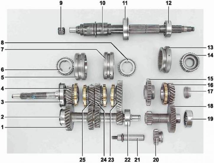
Shafts and gears of the five-speed gearbox: 1 - intermediate shaft (2107-1701050); 2 - front bearing of the intermediate shaft (2101-1701068): 3 - rear bearing of the primary shaft (2101-1701033); 4 - primary shaft with fourth gear pinion (2105-1701020); 5 - synchronizer clutch of III and IV gears (2101-1701116); 6 - synchronizer clutch hub (2101-1701119); 7 - 1st and 2nd gear synchronizer clutch (2101-1701116); 8 - synchronizer clutch hub (2101-1701119); 9 - Front roller bearing of the secondary shaft (2101-1701108-01); 10 - secondary shaft (2107-1701105-10); 11 - secondary shaft intermediate bearing (2101-1701190); 12 - Secondary shaft rear bearing (20715580); 13 - V-gear synchronizer clutch (2107-1701176); 14 - synchronizer clutch hub (2108-1701148); 15 - reverse gear pinion (2107-1701140); 16 - V-gear synchronizer gear (2107-17011157); 17 - speedometer drive gear (2106-1702158); 18 - block of gears of the 5th gear and reverse gear (2107-1701157); 19 - gear block bearing (2108-1701031-04); 20 - intermediate reverse gear (2121-1701080); 21 - reverse intermediate gear axle (2107-1701092); 22 - intermediate shaft rear bearing (2107-1701073-02); 23 - gear with synchronizer of 1st gear (2105-1701112); 24 - gear with synchronizer of the 2nd gear (2101-1701127); 25 - gear with synchronizer of the 3rd gear (2101-1701131)
helical gear of the transmission and the toothed ring of the synchronizer, with blocking rings fixed to them. The gears of the transmissions are in constant engagement with the corresponding gears of the intermediate shaft and the gear block of the 5th gear, and the reverse gear.
Intermediate shaft is made in the form of a block of four gears and rotates in bearings installed in the front and rear walls of the crankcase. The intermediate shaft drive gear is in constant engagement with the primary shaft gear. The V-gear and reverse gear gear block is attached to the rear end of the intermediate shaft with a bolt. The other end of the block rests on a bearing in the wall of the rear cover of the gearbox crankcase.
On the secondary shaft splines the reverse gear gear is installed between the rear wall of the crankcase and the V-gear pinion. The reverse gears are connected via an intermediate gear mounted on the axle, with the possibility of axial movement. The axle is secured with a nut on the rear wall of the crankcase. The gear engagement fork enters the annular groove of the gear; when it moves, the intermediate gear engages with the reverse gears.
The hubs of the synchronization clutches are fixedly mounted on the secondary shaft. The projections on the inner surface of the hubs of the synchronization clutches of the 1st - 2nd and 3rd - 4th gears enter three grooves on the shaft, and the hub of the 5th gear clutch is put on the splined part of the shaft. The synchronization clutch is put on the outer toothed rim of the hub with its inner toothed rim, forming an engagement with the clutch.
Gear shift forks enter the annular grooves on the outer side of the synchronization clutches. When the rod moves, the fork displaces the clutch. The clutch, acting on the locking ring of the synchronizer, shifts it. Under the action of friction forces arising between the clutch and the locking ring of synchronization, the speed of rotation of the gear and the hub is equalized. The teeth on the gear synchronization clutch engage with the teeth of the gear synchronization ring. The torque is transmitted from the gear through the clutch and hub to the secondary shaft.
(The original can be viewed on the portal VazBook)
Four-speed gearbox differs in the shape of the rear cover. The gearbox does not have a driven gear with a synchronizer and a V-gear synchronization clutch. The leading reverse gear is secured to the intermediate shaft tail with a retaining ring.