




Open large image in new tab »
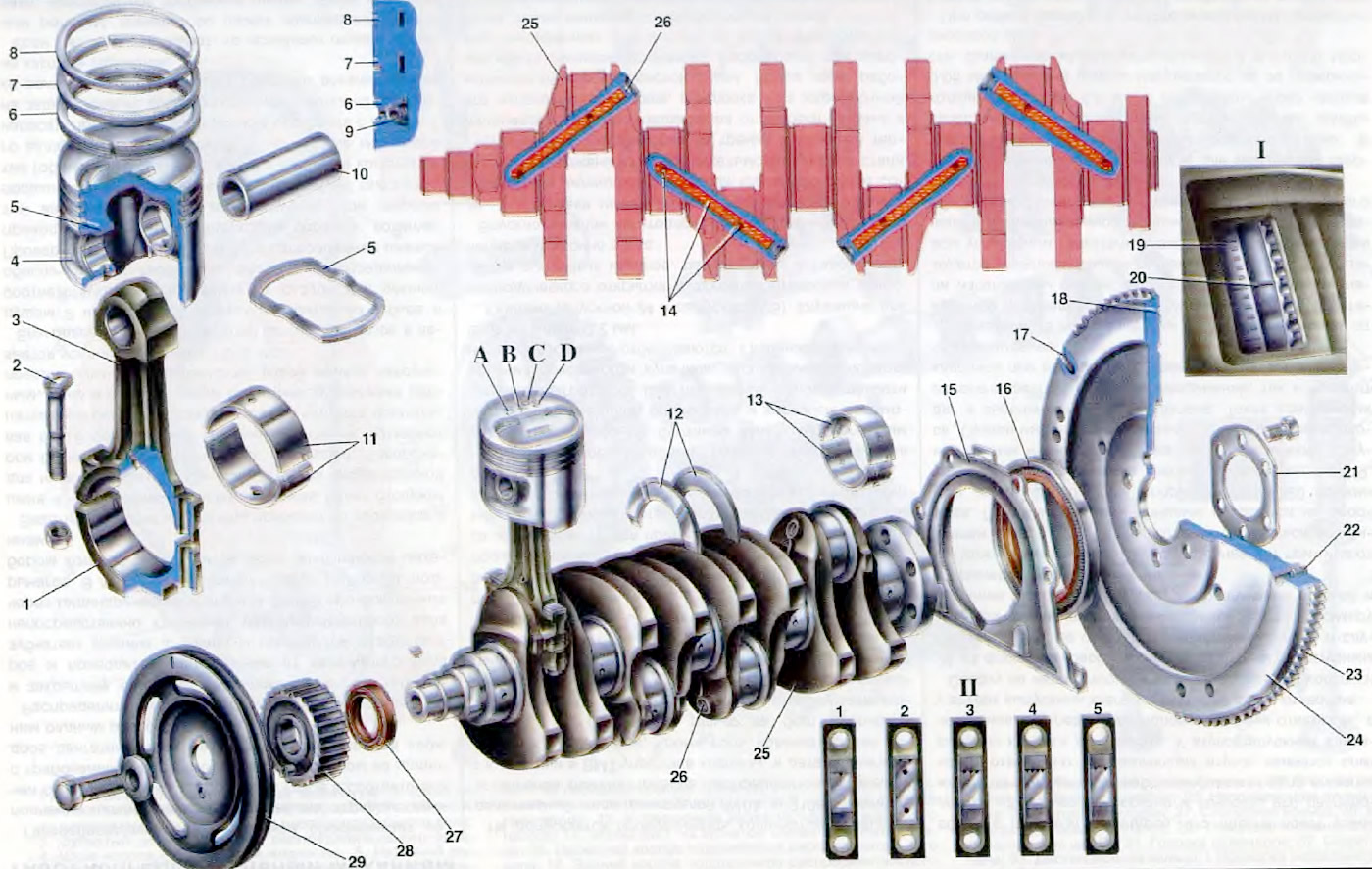
Figure 8. Crank mechanism: 1. Connecting rod cap; 2. Connecting rod cap mounting bolt; 3. Connecting rod; 4. Piston; 5. Piston thermostat plate: 6. Oil scraper ring; 7 Lower compression ring; 8. Upper compression ring; 9. Expansion spring; 10. Piston pin; 11. Connecting rod bearing shell; 12. Thrust half rings of the middle main bearing; 13 Main bearing shells; 14 Channels for supplying oil from the main bearing to the connecting rod; 15 Crankshaft rear oil seal holder; 16. Rear crankshaft oil seal; 17. Pin for TDC sensor; 18. Mark (hole) TDC of pistons of the 1st and 4th cylinders; 19. Scale in the clutch housing hatch, 20. TDC mark for pistons of the 1st and 4th cylinders on the flywheel rim; 21. Flywheel mounting bolt washer; 22. Clutch mounting pin; 23. Toothed flywheel rim; 24. Flywheel; 25. Crankshaft; 26. Crankshaft oil channel plug; 27. Front crankshaft oil seal (pressed into the oil pump cover); 28. Timing pulley of the camshaft drive; 29. Generator drive pulley; A. Marking of piston category by piston pin bore; B. Marking of piston class by outside diameter; C. Marking of piston repair size; D. Installation mark; I. Marks for setting the ignition timing. II. Marking the crankshaft main bearing caps (the bearing count is from the front of the engine).
The crank mechanism serves to convert the translational motion of the piston under the action of the expansion energy of the combustion products into the rotational motion of the crankshaft. The mechanism consists of a piston with piston rings and a pin, a connecting rod, a crankshaft and a flywheel.
Piston 4 is cast from a high-strength aluminum alloy. Since aluminum has a high temperature coefficient of linear expansion, a temperature-regulating steel plate 5 is cast in the piston head above the piston pin hole to eliminate the risk of the piston jamming in the cylinder.
Pistons, just like cylinders, are sorted into five classes by outer diameter:
| Class | Piston diameter of engines 2108 and 21081 | Piston diameter of engines 21083 |
| A | 75,965-75,975 | 81,965-81,975 |
| IN | 75,975-75,985 | 81,975-81,985 |
| WITH | 75,985-75,995 | 81,985-81.995 |
| D | 75,995-76,005 | 81,995-82,005 |
| E | 76,005-76,015 | 82,005-82,015 |
The piston diameter can be measured to determine its class only in one place: in the plane perpendicular to the piston pin at a distance of 51.5 mm from the piston bottom. In other places, the piston diameter differs from the nominal one, because the outer surface of the piston has a complex shape. In cross-section, it is oval, and in height, it is conical. This shape allows for compensation of uneven expansion of the piston due to uneven distribution of metal mass inside the piston.
The outer surface of the piston has annular microgrooves up to 14 microns deep. Such a surface facilitates better running-in of the piston, as oil is retained in the microgrooves. In the lower part of the piston pin bosses there are holes for the passage of oil to the piston pin. To improve lubrication conditions, two longitudinal grooves 3 mm wide and 0.7 mm deep are made in the upper part of the pin holes, in which oil accumulates.
The axis of the hole for the piston pin is shifted by 1.2 mm from the diametrical plane of the piston towards the location of the engine valves. Due to this, the piston is always pressed against one wall of the cylinder, and knocks of the piston on the cylinder walls when it passes through TDC are eliminated. However, this requires installing the piston in the cylinder in a strictly defined position. When assembling the engine, the pistons are installed so that the arrow on the piston bottom is directed towards the front of the engine.
By weight, pistons are sorted into three groups: normal, increased by 5 g and decreased by 5 g. These groups correspond to the markings on the piston bottom; "G", "+" and "-". All pistons on an engine must be of the same mass group to reduce vibrations due to the different masses of the reciprocating moving parts.
Spare parts are supplied in nominal size pistons of only three classes: A, C and E. This is sufficient to select a piston for any cylinder during engine repair, since pistons and cylinders are divided into classes with some overlap. For example, a piston of class C can fit cylinders of classes B and D. The main thing when selecting a piston is to ensure the necessary installation clearance between the piston and the cylinder - 0.025-0.045 mm.
In addition to nominal size pistons, spare parts also include repair pistons with an outer diameter increased by 0.4 and 0.8 mm. The bottoms of repair pistons are marked with a square or triangle. The triangle corresponds to an increase in the outer diameter by 0.4 mm, and the square - by 0.8 mm.
Piston pin 10 steel, tubular section, pressed into the upper head of the connecting rod and rotates freely in the piston bosses. According to the outer diameter, the pins are sorted into three categories through 0.004 mm in accordance with the categories of pistons. The ends of the pins are painted in the appropriate color; blue is the first category, green is the second, and red is the third.
Piston rings provide the necessary cylinder sealing and remove heat from the piston to its walls. The rings are pressed against the cylinder walls under the action of their own elasticity and gas pressure. Three cast iron rings are installed on the piston - two compression rings 7, 8 (sealing) and one (lower) oil scraper 6, which prevents oil from entering the combustion chamber
The upper compression ring 8 operates under conditions of high temperature, aggressive impact of combustion products and insufficient lubrication, therefore, to increase wear resistance, the outer surface is chrome-plated and has a barrel-shaped generatrix to improve running-in.
The lower compression ring 7 has a groove at the bottom to collect oil during the piston's downward stroke, performing the additional function of an oil-scraping ring. The surface of the ring is phosphated to increase wear resistance and reduce friction against the cylinder walls.
The oil scraper ring has chromed working edges and a groove on the outer surface, which collects the oil removed from the cylinder walls. A steel coil spring is installed inside the ring, which expands the ring from the inside and presses it against the cylinder walls. Rings of repair sizes are manufactured (the same as pistons) with an outer diameter increased by 0.4 and 0.8 mm.
The connecting rod is made of steel, is processed together with the cover, and therefore they are not interchangeable separately. In order not to mix up the covers and connecting rods during assembly, they are stamped with the number of the cylinder in which they are installed. During assembly, the numbers on the connecting rod and cover must be on the same side.
Crankshaft 25 is cast from high-strength special cast iron and consists of connecting rod and main ground journals. To reduce deformations during engine operation, the shaft is made five-bearing and with a large overlap of the main and connecting rod journals. Channels 14 are drilled in the shaft body to supply oil from the main journals to the connecting rod journals. The technological outputs of the channels are closed with cap plugs 26.
To reduce engine vibrations, the shaft is equipped with counterweights cast as one piece with the shaft. They balance the centrifugal forces of the crank pin, connecting rod and piston that occur during engine operation. In addition, to reduce vibrations, the crankshaft is dynamically balanced by drilling out the metal in the counterweights.
[Information copied from the portal: vazbook.ru]