




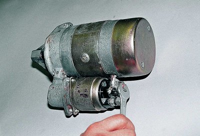
Using a 13 mm wrench, loosen the nut securing the wire to the traction relay...
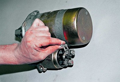
...and disconnect the wire tip.
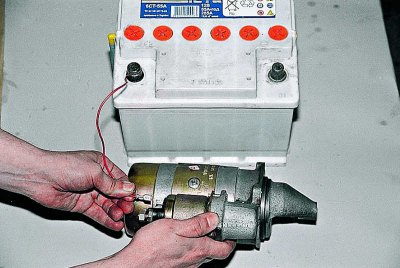
We apply 12 V voltage to the relay output,...
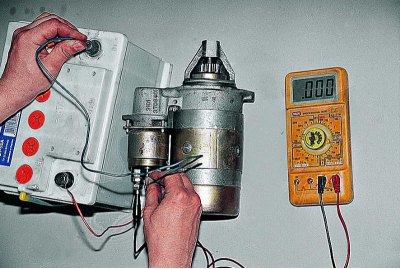
... "minus" - to the body, and connect the ohmmeter to the contact bolts. In this case, the anchor of a working relay should move the overrunning clutch into the window of the front cover, and the contact bolts should close. We replace the faulty traction relay with a new one.
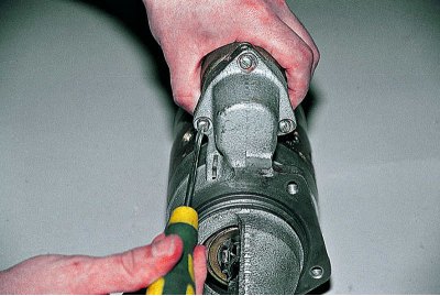
Using a Phillips screwdriver, unscrew the three screws...
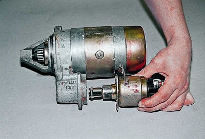
...and remove the traction relay.
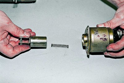
We remove the rod with the spring from the relay housing.
We install the new traction relay in the reverse order.
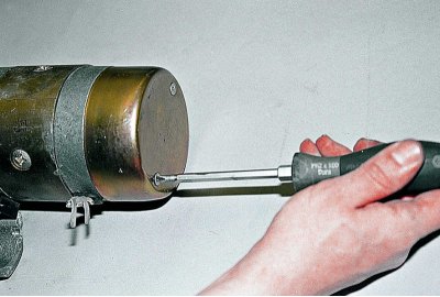
To further disassemble the starter, use a Phillips screwdriver to unscrew two screws...
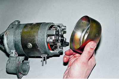
...and remove the lid.
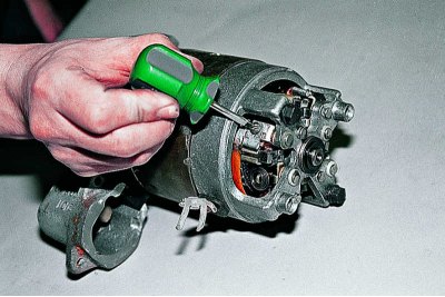
To check the condition of the brushes, use a slotted screwdriver to unscrew the screw securing the contact wire...
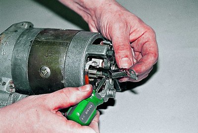
...and, pressing the spring with a screwdriver, we extract the brush. We extract the three remaining brushes in the same way. We replace the brushes that are worn to a height of 12 mm or less.
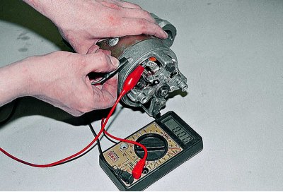
Connecting the ohmmeter to the stator winding terminals one by one, we check them for short circuits to the housing and for interturn short circuits. At the same time, we make sure that the free terminals of the windings are insulated from the housing.
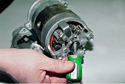
Using a screwdriver, remove the retaining ring.
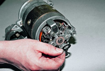
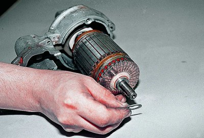
We remove the washer from the axle.
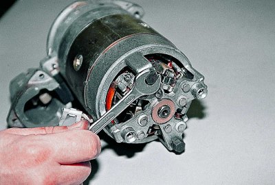
Using a 10 mm spanner, unscrew the two tie bolts...
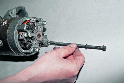
...and we take them out.
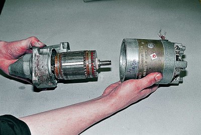
We separate the starter housing and remove the insulating tubes of the tie bolts from it.
We check the condition of the collector and windings by visual inspection. Charring of the windings is not allowed. If the collector is slightly burned, we clean its plates with fine abrasive paper. If there is severe burning and wear, it is better to replace the anchor. Scoring and dragging of bronze from the bearings on the anchor shaft journals is eliminated with the finest sandpaper followed by polishing.
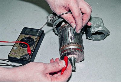
We check the anchor windings for short circuits with an ohmmeter. We replace the faulty anchor.
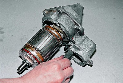
We remove the rubber seal from the drive cover.
The original can be seen on the website www.VAZbook.ru
Remove the adjusting washer from the anchor axis. It must be installed in place during assembly.
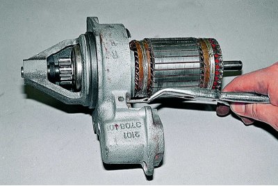
We remove the cotter pin from the lever axle.
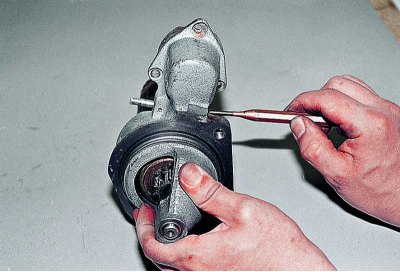
We knock out the axis with a beard...
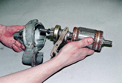
...and we take out the anchor with the drive.
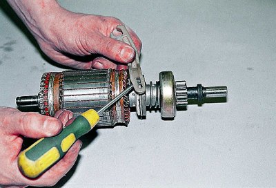
Using a screwdriver, we remove the overrunning clutch drive lever.
The gear should rotate easily in one direction and not rotate in the other, and should not have chips or nicks on the leading part of the teeth. If the gear is worn out or the clutch is faulty, we replace the entire assembly.
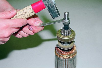
Having supported the anchor axis on a wooden block, we use a 13 mm wrench to knock the limiter off the locking ring.
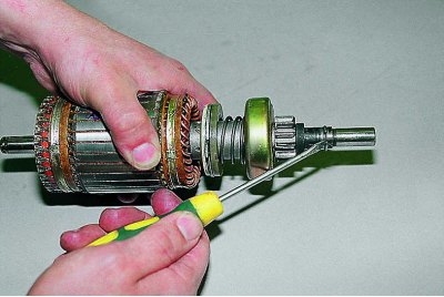
Using a screwdriver, remove the retaining ring.
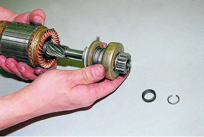
We remove the limiter and the overrunning clutch together with the drive gear from the axle.
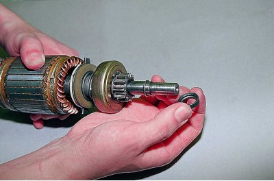
Having replaced the coupling assembly, we put the retaining ring in place and put the limiter with the conical groove towards the armature winding.
We press the limiter onto the retaining ring using a hammer blow through a 13 mm spanner.
Using compressed air, remove carbon dust from the housing and brush holder. Lubricate the drive ring and plastic surfaces in contact with it with Litol-24 or grease No.158. Lubricate the support bearings - rotor bushings, screw splines of the anchor shaft and the hub of the overrunning clutch with motor oil.
Further assembly is carried out in the reverse order of disassembly.
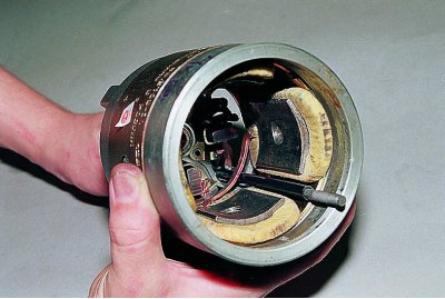
Before assembling the starter, insert the housing clamp bolts into the corresponding holes.
Attention! If only one bolt was insulated, when assembling the starter, we put the insulating tube on the one that can touch the copper busbar connecting the starter stator windings.
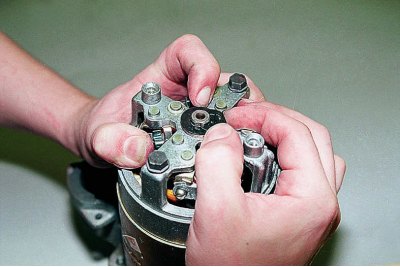
To snap the locking ring, press the starter anchor through the cover bushing from the drive side.