




Starter 35.3708 complete
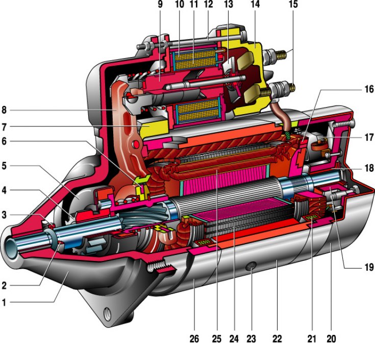
1 – drive side cover; 2 – retaining ring; 3 – limiting ring; 4 – drive gear; 5 – overrunning clutch; 6 – leash ring; 7 – rubber plug; 8 – drive lever; 9 – relay anchor; 10 – holding winding of the traction relay; 11 – pull-in winding of the traction relay; 12 – relay tension bolt; 13 – contact plate; 14 – relay cover; 15 – contact bolts; 16 – collector; 17 – brush; 18 – armature shaft bushing; 19 – cover from the collector side; 20 – casing; 21 – shunt coil of the stator winding; 22 – body; 23 – stator pole mounting screw; 24 - anchor; 25 – anchor winding; 26 – intermediate ring.
Starter Wiring Diagram
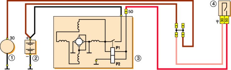
1 – generator; 2 – battery; 3 – starter; 4 – ignition switch; P1 – pull-in winding of the traction relay; P2 – holding winding of the traction relay.
[The original is on the portal: VazBook]
The starter is a four-pole, four-brush DC electric motor with mixed excitation, with a device for connecting and disconnecting the starter drive pinion with the flywheel ring gear. The starter is activated by an electromagnetic traction relay with remote control.
The starter is attached with three bolts to the clutch housing on the right side of the engine. A heat-insulating shield protects it from the heated exhaust pipe.
Technical characteristics of starter 35.3708* (ST–221)
| Nominal voltage, V | 12 |
| Nominal power, kW | 1,3 |
| Current consumption at maximum power, no more than, A | 290 (260**) |
| Current consumption in the inhibited state, no more than, A | 550 (500**) |
| Current consumption in idle mode, no more than, A | 60 (35**) |
* With end manifold.
** For starter ST-221.
The starter housing and covers are tightened with two bolts. Bronze-graphite bearings (bushings) are installed in the front and rear covers, in which the anchor shaft rotates.
The torque from the armature shaft is transmitted to the flywheel of the engine crankshaft through the starter drive.
The traction relay is used to engage the drive pinion with the flywheel ring gear and to turn on the power to the starter motor. When the ignition key is turned to the "starter" position, voltage is supplied to both windings of the traction relay (retracting and retaining). After the traction relay contacts are closed, the pull-in winding is switched off.
A freewheel roller clutch is installed on the drive shaft (overrunning clutch) with a drive pinion. It transmits torque in only one direction - from the starter to the engine, disengaging them after the engine starts. This is necessary to protect the starter from damage due to excessive rotation speed.
The drive's serviceability is determined by visual inspection after disassembling the starter. The stator, rotor and traction relay are checked for short circuits and winding breaks. The faulty element is replaced as an assembly. By visual inspection, we check the condition of the collector and brushes - we replace worn brushes, wipe the oily collector with white spirit, solvent or gasoline.