




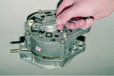
Using a 10 mm wrench, unscrew the nut...
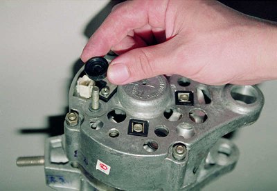
...and remove the insulating washer from the generator terminal "30".
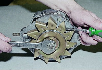
Using a 19 mm spanner, unscrew the generator pulley nut. Using a screwdriver, hold the rotor from turning by the impeller protrusion (do not bend the blades).
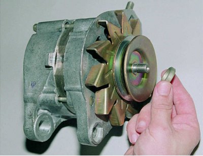
We remove the washer,...
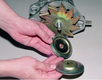
...pulley parts,...
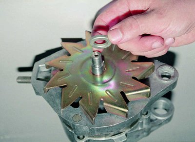
...adjustment ring...
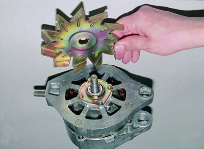
...and the impeller.
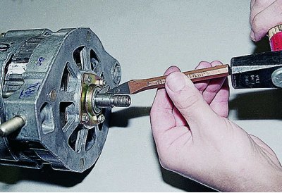
Using a small chisel, we remove the key from the shaft groove...
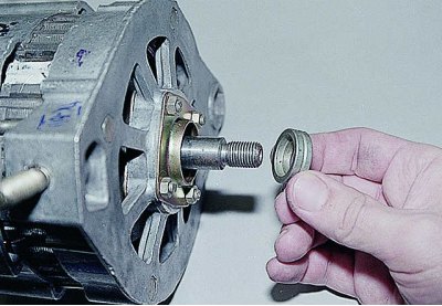
...and remove the ring installed behind it.
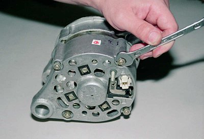
Using a 10 mm spanner, unscrew the four nuts...
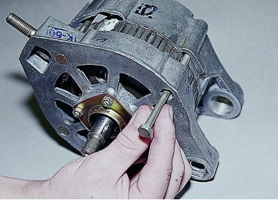
...and we remove the bolts that hold the generator covers together.
The article is taken from an online resource: vazbook
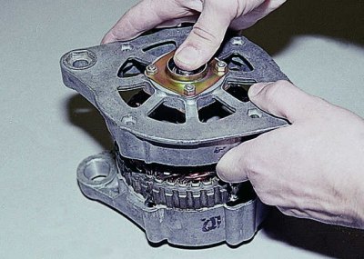
Remove the front cover.
If the rotor shaft fits tightly in the bearing, holding the generator by the front cover, knock out the axle through a mandrel made of soft metal.
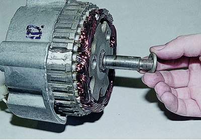
Remove the adjusting washer. When assembling, do not forget to install it in place.
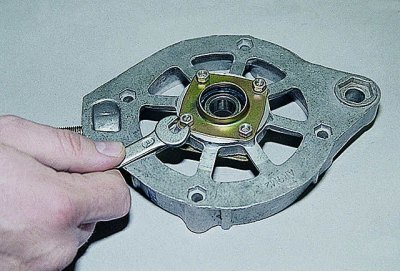
To replace the front bearing, use an 8 mm spanner to unscrew the four nuts. They were locked during assembly – the ends of the studs were crushed. If the nuts are damaged during unscrewing, new ones will be required during assembly.
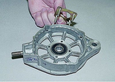
We remove the outer and inner covers together with the studs.
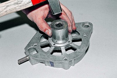
We knock out the front bearing using a mandrel.
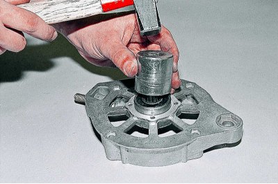
We install a new bearing by lightly tapping its outer ring through a mandrel, which can be a suitable head or sleeve.
We install the bearing caps, tighten the nuts...
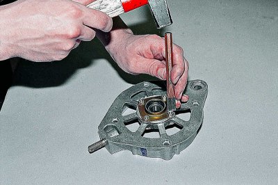
...and we counter them again with a punch or chisel.
Remove the brush holder (see Replacing generator brushes).
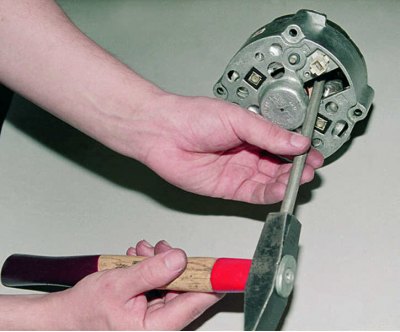
Using a soft metal punch, knock the rotor out of the rear cover. The rotor is removed together with the bearing.
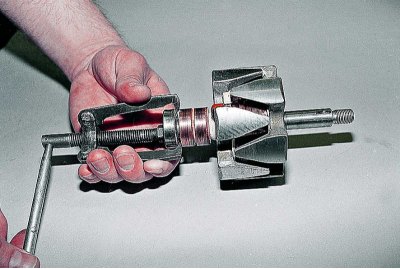
The rear bearing rarely needs to be replaced. If necessary, pull it off the rotor shaft with a puller.
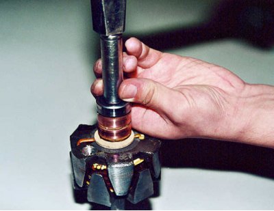
We press in the new bearing by striking it through the mandrel – and only on its inner ring.
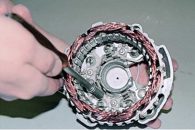
Using an 8 mm head, unscrew the three nuts securing the stator terminals to the rectifier unit.
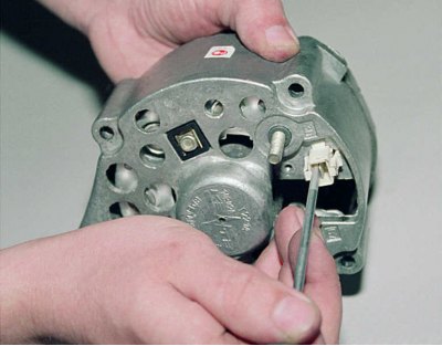
Using a thin screwdriver, press the lock of the "neutral" wire plug,...
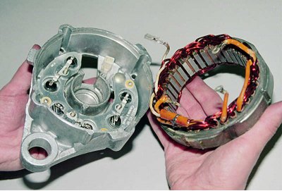
...we remove the stator.
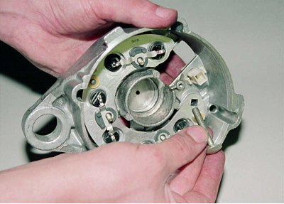
We take out the terminal bolt "30".
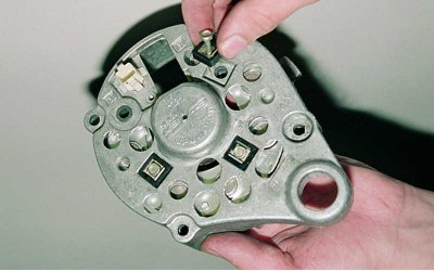
We remove three bolts from the back cover together with the insulating gaskets...
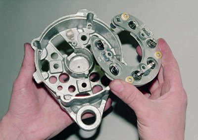
...and we take out the rectifier block.
For checking the rectifier unit, see section Checking the generator.
The valve (diode) has one-way conductivity. A faulty one usually passes current in both directions. Replacing individual valves is possible, but they will need to be re-pressed into the holder - an operation that requires accuracy and skill. Therefore, we recommend replacing the rectifier unit as a whole if its elements fail.
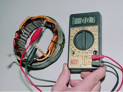
By connecting the ohmmeter probes to the stator terminals one by one, we check its windings for breakage...
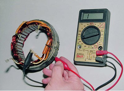
...and a short circuit to the body.
We replace the faulty stator
Before assembly, clean all parts from oil, dirt and carbon dust. Wipe contact rings with a cloth soaked in gasoline or solvent. In case of severe oxidation and burning, clean the rings with the finest sandpaper.
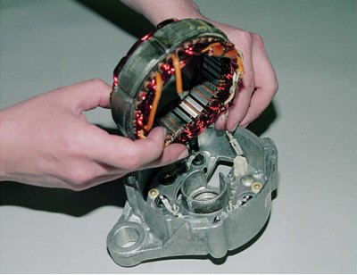
We assemble the generator in the reverse order of disassembly. Before installing the stator, we insert the plug of the "neutral" wire into the rear cover (having previously bent back its retainer) into the generator junction block.