




Attention! When checking with 220 V, be careful - do not touch the parts of the starter that are under voltage with your hands.
1. Clean all starter parts.
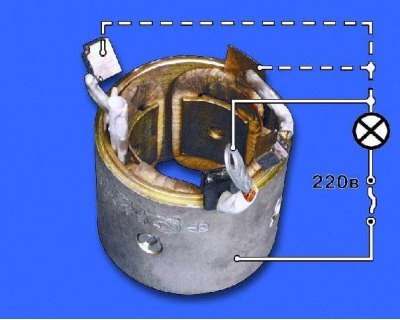
2. Check the condition of the stator winding. To do this, turn on the test lamp in the 220 V AC circuit and connect the wire to one of the stator winding terminals, short-circuit the other end of the circuit to the housing. If the lamp lights up, the winding insulation is damaged. Replace the winding or stator. Check the second winding in the same way (see note).
The stator windings can be checked with a megohmmeter. Connect one contact to the terminal and the other to the stator housing. The winding resistance should be at least 10 kOhm. If it is less, replace the stator.
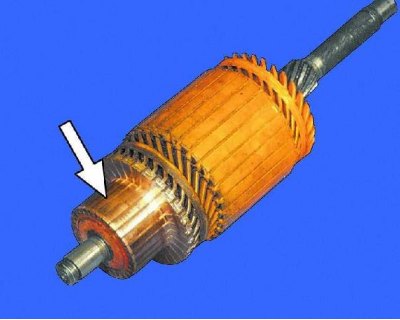
3. Inspect the anchor. If the commutator is dirty or has marks, scratches, etc., polish it with fine glass paper. If the commutator is significantly rough or if there are mica protrusions between the plates, turn the commutator on a lathe and then polish it with fine glass paper. The runout of the core relative to the shaft journals should not exceed 0.08 mm. If the runout is greater, replace the anchor.
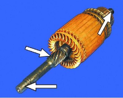
4. If you find yellow deposits from the bearing on the anchor shaft, remove them with fine sandpaper, otherwise this will cause the gear to jam on the shaft. If there are nicks or burrs on the surfaces of the journals and splines of the shaft, replace the anchor.
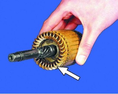
5. Check the reliability of the soldering of the anchor winding terminals to the collector plates. Inspect the winding at the ends of the anchor: the winding diameter should be smaller than the anchor iron package. If the diameter is larger, replace the anchor.
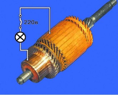
6. Check the condition of the armature winding with a test lamp in the 220 V AC circuit. Connect the wires to the collector plate and the armature core. If the lamp lights up, then there is a short circuit in the armature winding or the collector plate to ground. In this case, the armature must be replaced (see note).
Note to operation 6. The armature windings can be checked with a megohmmeter. Connect one of its contacts to the collector, the other to the armature core. The resistance of the windings should be no less than 10 kOhm. If the resistance is less, replace the armature.
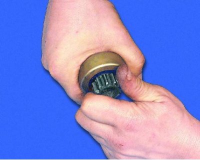
7. While holding the overrunning clutch, try to turn the starter pinion in both directions: it should rotate freely only clockwise. If the pinion rotates in both directions, replace the drive.
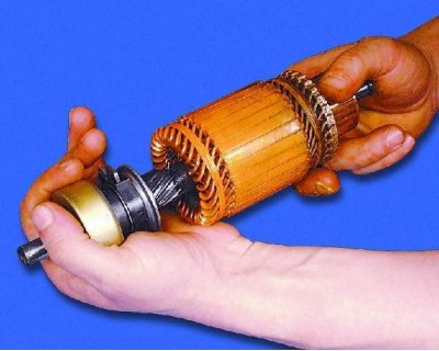
8. Place the starter drive on the armature shaft. It should move freely along the shaft splines without jamming.
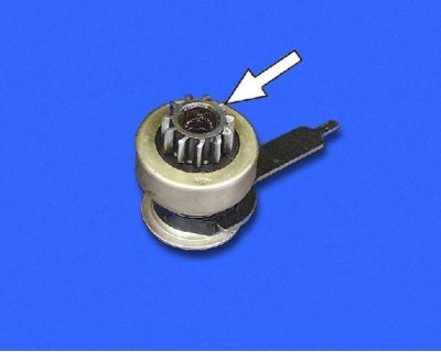
9. If the drive parts are badly worn or damaged, replace the drive. If nicks are found on the lead-in part of the gear teeth, grind them with a fine-grained emery wheel of small diameter.
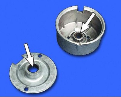
10. Inspect the starter cover on the collector side and the intermediate support. If cracks appear on these parts, replace them. Also inspect the bushings in the cover and in the support in which the anchor shaft rotates. If severe wear or mechanical damage is detected, replace the cover or support with defective bushings.
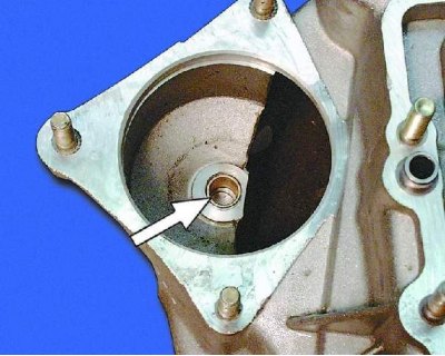
11. Inspect the bushing pressed into the clutch housing. If the bushing is worn or has burrs, cavities, etc., replace the bushing.
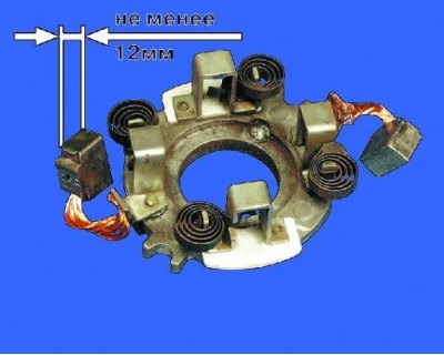
12. Brushes worn to a height of less than 12 mm must be replaced.
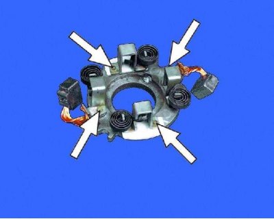
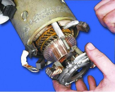
13. Check the movement of the brushes in the holders: the brushes should move easily, without jamming. Check the reliability of the fastening of the brush holders: they should be firmly secured.
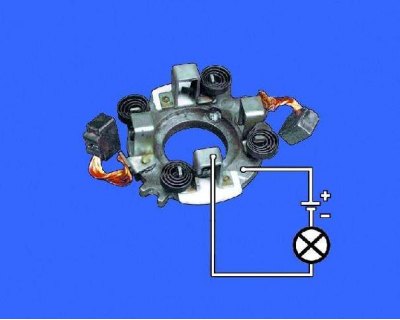
14. The insulated brush holders must not have a short circuit to ground. Check this with a test lamp.
(The text is copied from the online portal: «www.VazBook.ru»)
15. Check the force of the springs pressing the brushes using a dynamometer. To do this, insert the anchor into the cover from the drive side, install the housing and brush holder. Insert the brushes into the brush holders. At the moment the spring breaks away from the brush, the force should be within 9.0–11.0 N (0.9–1.1 kgf).
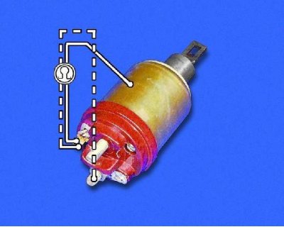
16. Check the resistance of the traction relay windings with an ohmmeter. The resistance of the pull-in winding should be within 0.52–0.59 Ohm (red), and the holding one – 0.725–0.795 Ohm (yellow) at an ambient temperature of 15 to 25°C. The traction relay anchor must move freely in the housing, without jamming.
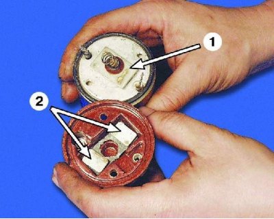
1 – contact plate
2 – rectangular heads of contact rings
Note. At the same time as checking the winding resistance, check whether the contact plate closes the contact bolts of the traction relay. If the ohmmeter shows "∞", then either there is a break in the winding, or the plate does not close the contact bolts. In both cases, the traction relay must be replaced.
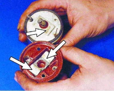
17. Inspect the contact bolts. Clean the burnt bolt heads with fine sandpaper. If the heads are heavily burnt, you can turn the bolts 180° so that they are pressed against the contact plate with the unburnt side. If the surface of the contact plate is heavily worn, it can be turned with the other side facing the contact bolts.