




Open large image in new tab »
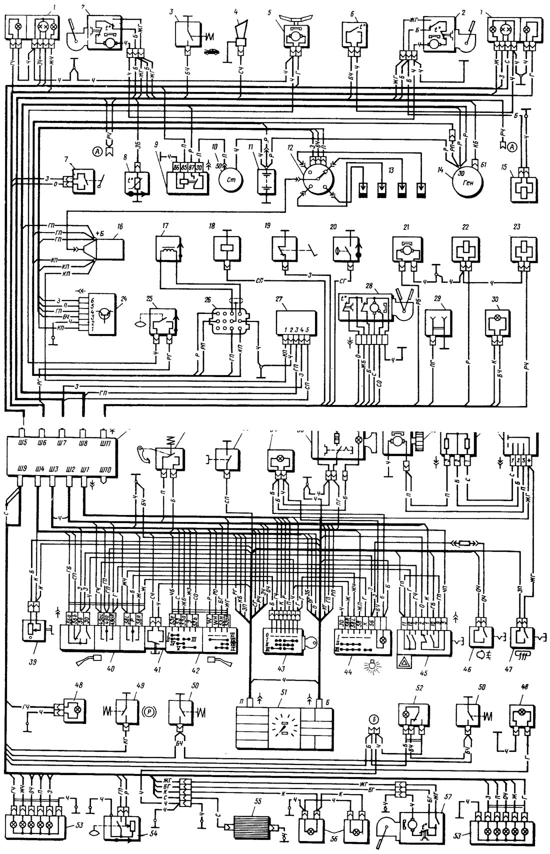
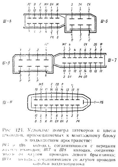
Figure 123. Electrical equipment diagram of the VAZ-2108: 1 - headlight, 2 - headlight washer motor*; 3 - underhood lamp switch; 4 - sound signal; 5 - Electric motor of the cooling system fan; 6 - fan motor switch sensor; 7 - Reverse light switch; 8 - temperature indicator sensor; 9 - starter relay; 10 - starter; 11 - battery; 12 - ignition distributor sensor; 13 - spark plugs; 14 - generator; 15 - electromagnetic valve for switching on headlight washer*; 16 - ignition coil; 17 - TDC sensor of the piston of the 1st cylinder (with shielded wires); 18 - carburetor electromagnetic valve; 19 - carburetor limit switch; 20 - Oil pressure warning light sensor; 21 - Washer motor; 22 - electromagnetic valve for turning on the windshield washer; 23 - electromagnetic valve for turning on the rear window washer*; 24 - Switch; 25 - brake fluid level sensor; 26 - diagnostic socket; 27 - carburetor electromagnetic valve control unit; 28 - Windscreen wiper motor; 29 - Portable lamp socket; 30 - underhood lamp; 31 - mounting block (see figure 124-126); 32 - brake light switch; 33 - Carburetor air damper indicator lamp switch; 34 - heater lever illumination panel; 35 - cigarette lighter; 36 - heater electric motor; 37 - additional resistor of the heater electric motor; 38 - heater motor switch; 39 - Instrument lighting switch; 40 - direction indicator, headlight and parking light switch; 41 - Sound signal switch; 42 - Windscreen wiper and washer switch; 43 - ignition switch; 44 - Outdoor lighting switch; 45 - Hazard warning switch; 46 - fog light switch, 47 - rear window heating switch; 46 - side direction indicator; 49 - Parking brake indicator lamp switch; 50 - Ceiling light switch in the door pillar; 51 - instrument cluster; 52 - lampshade; 53 - rear light; 54 - Fuel level and reserve indicator sensor; 55 - rear window heating element; 56 - Number plate lights; 57 - Rear window wiper*; A - wire tip for connection to brake pad wear sensor*; B - connector for connection to an individual interior light*
*Only on some vehicles.
 |
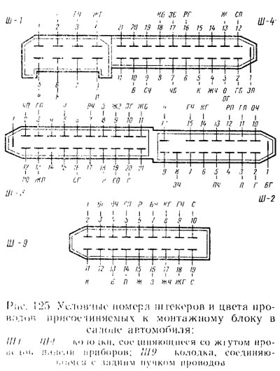 |
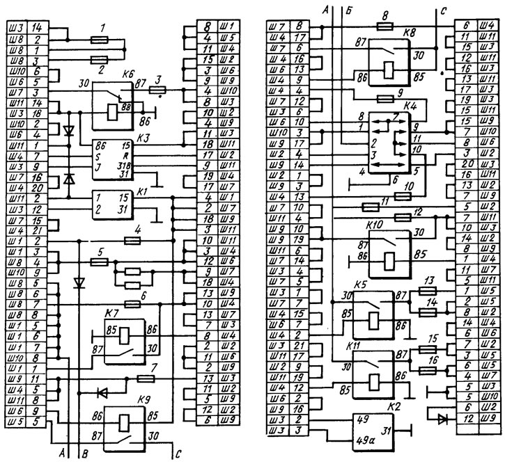
Figure 126. Wiring diagram of the mounting block (the outer number in the wire tip designation is the block number, and the inner number is the conventional plug number): K1 - rear window washer time relay; K2 - relay-interrupter of direction indicators and hazard warning lights; K3 - windshield wiper relay; K4 - lamp health control relay (inside are shown contact jumpers that are installed instead of the relay); K5 - high beam headlight relay; K6 - headlight cleaner relay; K7 - window lifter power relay (not installed on VAZ-2108); K8 - sound signal relay; K9 - relay for switching on the electric motor of the cooling system fan; K10 - rear window heating relay; K11 - low beam headlight relay
(The text is copied from the online resource: «VazBook.ru»)