
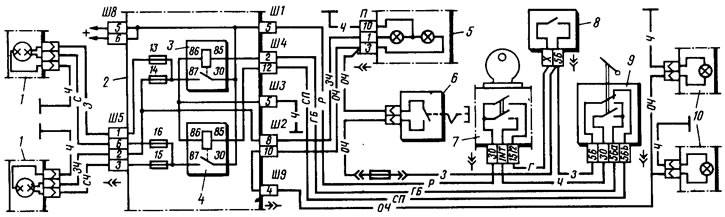
Pic. 144. Scheme of inclusion of headlights and fog light: 1 - block headlights (fragment); 2 - mounting block (fragment); 3 - relay for switching on high beam headlights; 4 - relay for turning on the dipped headlights; 5 - instrument cluster with control lamps for high beam headlights - on the left - and fog light - on the right (fragment); 6 - fog snow switch in the rear lights; 7 ignition switch (fragment); 8 - outdoor lighting switch; 9 - headlight switch; 10 - fog lamps in the rear lights (fragment)
Irrespective of the position of the switch button 8, you can briefly turn on the main beam by pulling the headlight switch lever towards you. In this case, the voltage to the contact «30» switch 9 is supplied from contact «1NT» ignition switch.
On some cars, a hydraulic headlight corrector is installed. It serves to adjust the angle of the headlights depending on the load on the car. The hydraulic corrector consists of a master cylinder mounted on the instrument panel, slave cylinders mounted on the headlights, and connecting tubes. The cylinders and tubes contain a special fluid that does not freeze at low temperatures.
Outdoor Lighting
The switching circuit is shown in fig. 145. The side light is switched on by the switch 10 for outdoor lighting. The parking light is switched on by switch 8 if the key of ignition switch 6 is in position III (parking). At the same time, the side light lamps of the left or right side of the vehicle light up, depending on the position of switch 8.
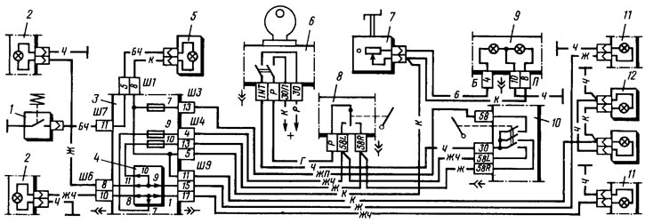
Pic. 145. Scheme for switching on outdoor lighting: 1 - engine compartment lamp switch; 2 - side light lamps in block headlights; 3 - mounting block (fragment); 4 - contact jumpers at the installation site of the lamp control relay; 5 - engine compartment lamp; 6 - ignition switch (fragment); 7 - instrument lighting switch; 8 - parking light switch; 9 - instrument cluster with instrument lighting lamps (left) and a control lamp for outdoor lighting (on right); 10 - outdoor lighting switch; 11 - side light lamps in the rear lights; 12 - license plate lights
Direction indicators and alarms
The switching circuit is shown in fig. 146. The right or left side direction indicators are switched on by switch 6. In the alarm mode, switch 8 turns on all direction indicators. The flashing of the lamps is provided by the relay-breaker 4.
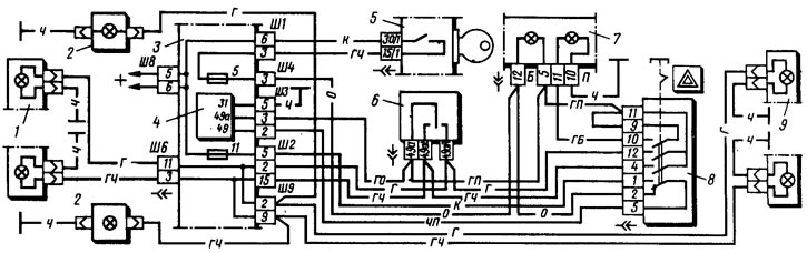
Pic. 146. The scheme of inclusion of direction indicators and alarms: 1 - direction indicator lamps in headlights; 2 - side direction indicators; 3 - mounting block (fragment); 4 - relay-breaker for direction indicators and alarms; 5 - ignition switch; 6 - turn signal switch; 7 - a combination of devices with control lamps of direction indicators (left) and alarm (on right); 8 - alarm switch; 9 - turn signal lamps in the rear lights
Sound signal
The car is equipped with a sound signal C309 or C308. If the signal strength decreases or wheezing appears, adjust the signal by turning the screw on its body in one direction or another until a loud and clear sound is obtained. If the adjustment does not eliminate wheezing or the signal is intermittent, then the signal is disassembled and the breaker contacts are cleaned. When assembling the signal, the old gasket is installed between the membrane and the signal housing so as not to disturb the gap (1,15±0,05) mm between core and armature. If the signal does not turn on, then check the reliability of the wire connection, the condition of the contacts of the switch and relay in the mounting block. Clean contacts if necessary.
Possible malfunctions of lighting and light signaling are given in tab. 23.